Raster microscope

a raster microscope and microscope technology, applied in the field of raster microscopes, can solve the problems of having to adjust and adapt the optical components, and achieve the effect of reducing the adjustment requirements

Inactive Publication Date: 2009-10-06
LEICA MICROSYSTEMS CMS GMBH
View PDF16 Cites 12 Cited by
  • Summary
  • Abstract
  • Description
  • Claims
  • Application Information

AI Technical Summary

Benefits of technology

[0014]Therefore, it is an object of the present invention to provide a scanning microscope with which a theoretically possible degree of resolution can be achieved with considerably reduced adjustment requirements and which concurrently offers a simplified adaptation to changing examination conditions, for instance, the changing of objectives.
[0016]The invention entails the advantage that at least one optical system is provided that images the optical component into the pupil of the objective, whereby the size of the image of the optical component can be adjusted.

Problems solved by technology

A drawback of this approach is that the optical component has to be readjusted and adapted to the structural and optical properties of the new objective every time the objective is changed.

Method used


Image

  • Raster microscope
  • Raster microscope
  • Raster microscope

Examples


Embodiment Construction

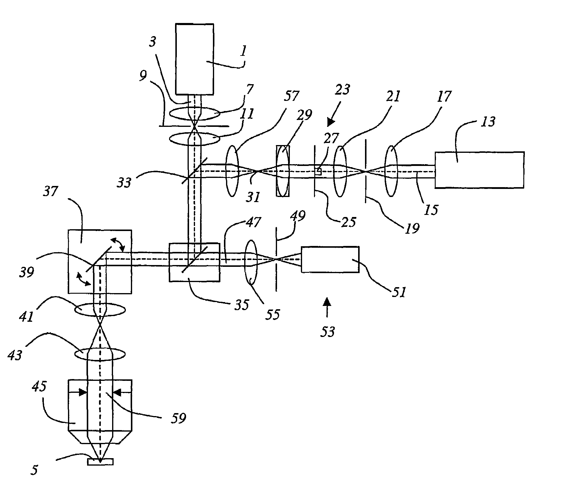
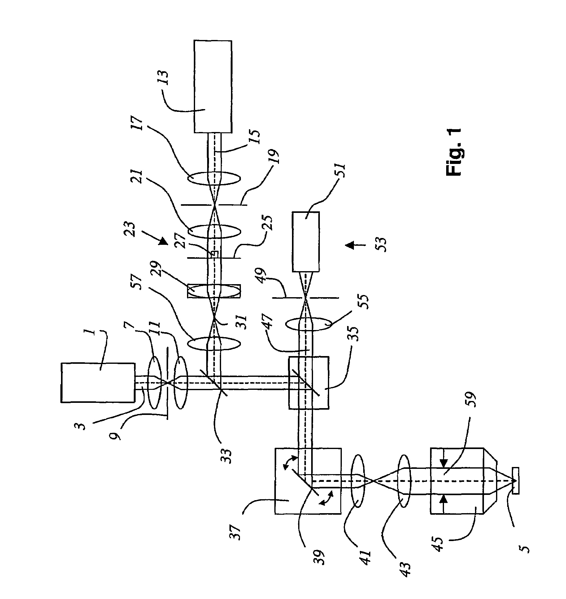
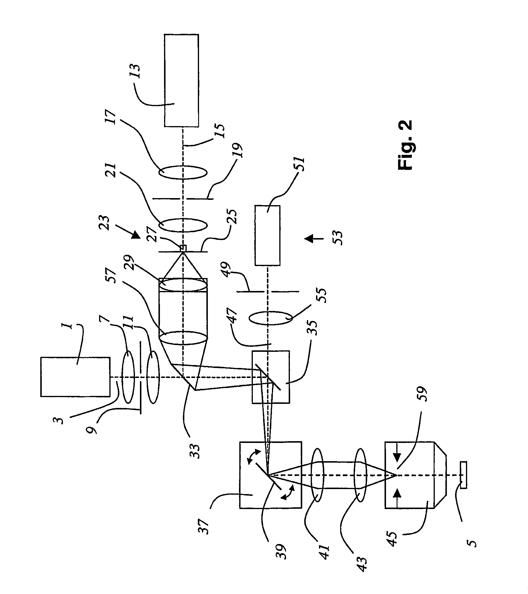
[0029]FIG. 1 shows a scanning microscope according to the invention that is configured as a confocal scanning microscope. The scanning microscope comprises a first light source 1 that emits an excitation light beam 3 to optically excite a first area of a specimen 5. The excitation light beam 3 is focused with the optical system 7 onto the illumination pinhole diaphragm 9, it passes through the latter and is subsequently collimated by the next optical system 11. The scanning microscope comprises another light source 13 that generates a stimulation light beam 15 that is focused onto the stimulation pinhole diaphragm 19 with the lens 17. The stimulation light beam 15 that passes through the stimulation pinhole diaphragm 19 is collimated by the next lens 21 and subsequently passes through an optical component 23 for purposes of influencing the shape of the focus of the stimulation light beam 15. The optical component 23 consists of a substrate 25 onto which a phase-retardation plate 27 ...


PUM


Abstract

A scanning microscope includes an excitation light beam, a stimulation light beam, an objective, an optical component and an optical system, The excitation light beam optically excites a first area of a specimen. The stimulation light beam triggers a stimulated emission or an additional excitation in a second area of the specimen, the second area at least partially overlapping with the first area of the specimen. The objective focuses the excitation light beam and the stimulation light beam. The optical component influences a shape of the focus of the excitation light beam and / or of the stimulation light beam. The optical system images the optical component into the pupil of the objective and adjusts a size of an image of the optical component.

Description

[0001]The invention relates to a scanning microscope with an excitation light beam to optically excite a first area of a specimen, with a stimulation light beam to trigger a stimulated emission or an additional excitation in another area of the specimen that at least partially overlaps with the first area of the specimen, comprising at least one objective to focus the excitation light beam and the stimulation light beam and an optical component to influence the shape of the focus of the excitation light beam and / or of the stimulation light beam.BACKGROUND[0002]In scanning microscopy (raster microscopy), a specimen is illuminated with a light beam so that the reflection light or fluorescent light emitted by the specimen can be observed. The focus of the illuminating light beam is moved in an object plane by means of a controllable beam deflector, generally by tilting two mirrors, whereby the deflection axes are usually positioned perpendicular to each other, so that one mirror deflec...

Claims


Application Information

Patent Timeline
Patent Type & Authority Patents(United States)
IPC IPC(8): G02B21/06G02B21/00
CPCG02B21/0024G02B21/006G02B21/0032
Inventor GUGEL, HILMAR
Owner LEICA MICROSYSTEMS CMS GMBH
Why Eureka
Try Eureka