Device and method for increasing focused power density of high-energy petawatt laser

A high-energy petawatt and power density technology, applied in optics, optical components, instruments, etc., can solve problems affecting wavefront measurement, affecting focusing effect, increasing system cost, etc., to avoid wavefront distortion, improve focusing ability, adjust Simple and convenient effect

Active Publication Date: 2014-10-01
SHANGHAI INST OF OPTICS & FINE MECHANICS CHINESE ACAD OF SCI
View PDF4 Cites 0 Cited by
  • Summary
  • Abstract
  • Description
  • Claims
  • Application Information

AI Technical Summary

Problems solved by technology

[0009] Secondly, due to the limitation of the caliber of the measuring instrument, the wavefront of the medium and large spot cannot be directly measured. Generally, the spot is reduced by a beam reduction imaging system to match the aperture of the wavefront detector. This requires that the beam reduction imaging system cannot Introduce additional wavefront distortion, otherwise it will affect the real wavefront measurement;
[0010] Thirdly, since the measured wavefront is before the focusing optical element or even the compressing optical element, even if the wavefront at the measurement position is corrected to a plane wavefront, it cannot guarantee that the laser spot can be focused close to the diffraction limit, because the spot will go through the Focusing element, the processing accuracy and adjustment accuracy of the focusing element itself will inevitably introduce new wavefront distortion, which will degrade the corrected wavefront and affect the final focusing effect;
[0011] Finally, in this device, the deformable mirror is placed behind the grating. Usually, the diameter of the spot here is very large. For high-energy petawatt systems, it is generally larger than 120mm. Only large-diameter deformable mirrors are required to achieve the purpose of wavefront correction. cost of the system
Therefore, if the traditional adaptive optics wavefront correction loop wants to achieve a better correction effect and obtain a focal spot close to the diffraction limit, it must not only use a large-diameter deformable mirror to correct the spot at the measured position to an ideal plane wavefront, but also It is necessary to fine-tune the beam reduction imaging system and focusing components to avoid introducing new wavefront distortions that affect measurement and calibration results
It has relatively high requirements for other related devices and adjustment accuracy in the application of improving the focusing ability of high-energy laser systems, and the operation is more complicated

Method used


Image

  • Device and method for increasing focused power density of high-energy petawatt laser
  • Device and method for increasing focused power density of high-energy petawatt laser

Examples


Embodiment Construction

[0029] The present invention will be further described below in conjunction with the embodiments and accompanying drawings, but the protection scope of the present invention should not be limited thereby.

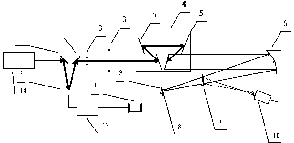
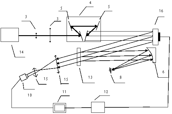
[0030] see figure 1 , figure 1 It is also an optical path diagram of an embodiment of the device for increasing the peak power density of a high-energy petawatt laser in the present invention. As can be seen from the figure, the device for improving the focusing power density of a large spot of a high-energy petawatt laser in the present invention includes a mirror group 1, a small-diameter deformable mirror 2, a beam expander system 3, an optical compression device 4, an off-axis parabolic mirror 6, a reflector A wedge mirror 7 with a rate of 5%, a wavefront detector 10, a high-resolution scientific CCD9, a computer 11 and a high-voltage power supply controller 12 for the deformable mirror. The device takes the wavefront detector 10 placed behind the focal point of the...


PUM


Abstract

Disclosed are a device for increasing high-energy petawatt laser focusing power density and a method. The device comprises a reflector group, a deformable lens, a beam expanding system, a compressor, a large-aperture off-axis parabolic lens, a wedge-shaped lens, a wavefront sensor, a high-resolution scientific CCD (charge coupled device), a computer and a deformable lens high-voltage power controller. The wavefront detector is placed at the rear of the focus of the large-aperture off-axis parabolic lens, the small-aperture deformable lens which is a correcting component is placed in a small-aperture optical path in front of the compressor, and the wavefront detector and the small-aperture deformable lens form an adaptive optical closed correcting loop which is used for measuring and correcting, with wavefront of a spherical surface behind the focus as a benchmark. The small-aperture deformable lens can effectively correct all wavefront distortions including wavefront distortions caused by an optical compressing element and an optical focusing element, the size of a focusing spot is close to diffraction limit as far as possible, and the laser focusing power density is greatly increased. The device has the advantages that the device is economical and high-efficient, is simple in adjustment and stable in operation, and the like.

Description

technical field [0001] The invention relates to high-energy petawatt laser focusing power density and adaptive optics technology, in particular to a device and method for improving high-energy petawatt laser focusing power density. Background technique [0002] Ultra-short and ultra-intensive laser science is an important scientific frontier with the development of ultra-short and ultra-intense laser technology, the interaction between ultra-short and ultra-intense laser and matter, and the frontier basic research in interdisciplinary and related high-tech fields. The field is the basis for realizing extreme physical conditions and revealing the essence of matter. [0003] Since the mid-1980s, high-power ultrashort pulse laser technology has developed rapidly, and major scientific and technological countries in the world, including my country, have successively established large-scale high-power ultrashort pulse laser devices. Ultra-short and ultra-intense lasers are known ...

Claims


Application Information

Patent Timeline
Patent Type & Authority Patents(China)
IPC IPC(8): G02B26/06G02B27/09
Inventor 梁晓燕於亮红任志君李儒新徐至展
Owner SHANGHAI INST OF OPTICS & FINE MECHANICS CHINESE ACAD OF SCI
Why Eureka
Try Eureka