Combined electro-mechanical and solid state switching fabric

a switching fabric and electro-mechanical technology, applied in data switching networks, instruments, frequency-division multiplexes, etc., can solve the problems of loss and inefficiency during both switchover and normal operation, ds signal quality degradation, and low signal quality, and achieve a high number of multiple redundant groupings

Inactive Publication Date: 2009-10-06
CISCO TECH INC
View PDF12 Cites 14 Cited by
  • Summary
  • Abstract
  • Description
  • Claims
  • Application Information

AI Technical Summary

Benefits of technology

[0008]According to various embodiments, the techniques of the present invention do not require the use of passive splitters and thus eliminate the additional insertion loss of those splitters while meeting channel to channel isolation in excess of 60 dB. The techniques and mechanisms also do not require the disabling of the downstream up-converters due to the isolation of the electromechanical relay thus eliminating the potential for co-channel interference during failsafe switchover.

Problems solved by technology

However, hardware mechanisms for switching the cable line over from a failed line card to a protect line card are limited.
In many instances, the hardware switching mechanisms cause loss and inefficiency during both switchover and normal operation.
Furthermore, the switches also require a 3 dB splitter or low isolation components which cause the DS signal quality to degrade.

Method used


Image

  • Combined electro-mechanical and solid state switching fabric
  • Combined electro-mechanical and solid state switching fabric
  • Combined electro-mechanical and solid state switching fabric

Examples


Embodiment Construction

[0021]Reference will now be made in detail to some specific embodiments of the invention including the best modes contemplated by the inventors for carrying out the invention. Examples of these specific embodiments are illustrated in the accompanying drawings. While the invention is described in conjunction with these specific embodiments, it will be understood that it is not intended to limit the invention to the described embodiments. On the contrary, it is intended to cover alternatives, modifications, and equivalents as may be included within the spirit and scope of the invention as defined by the appended claims.

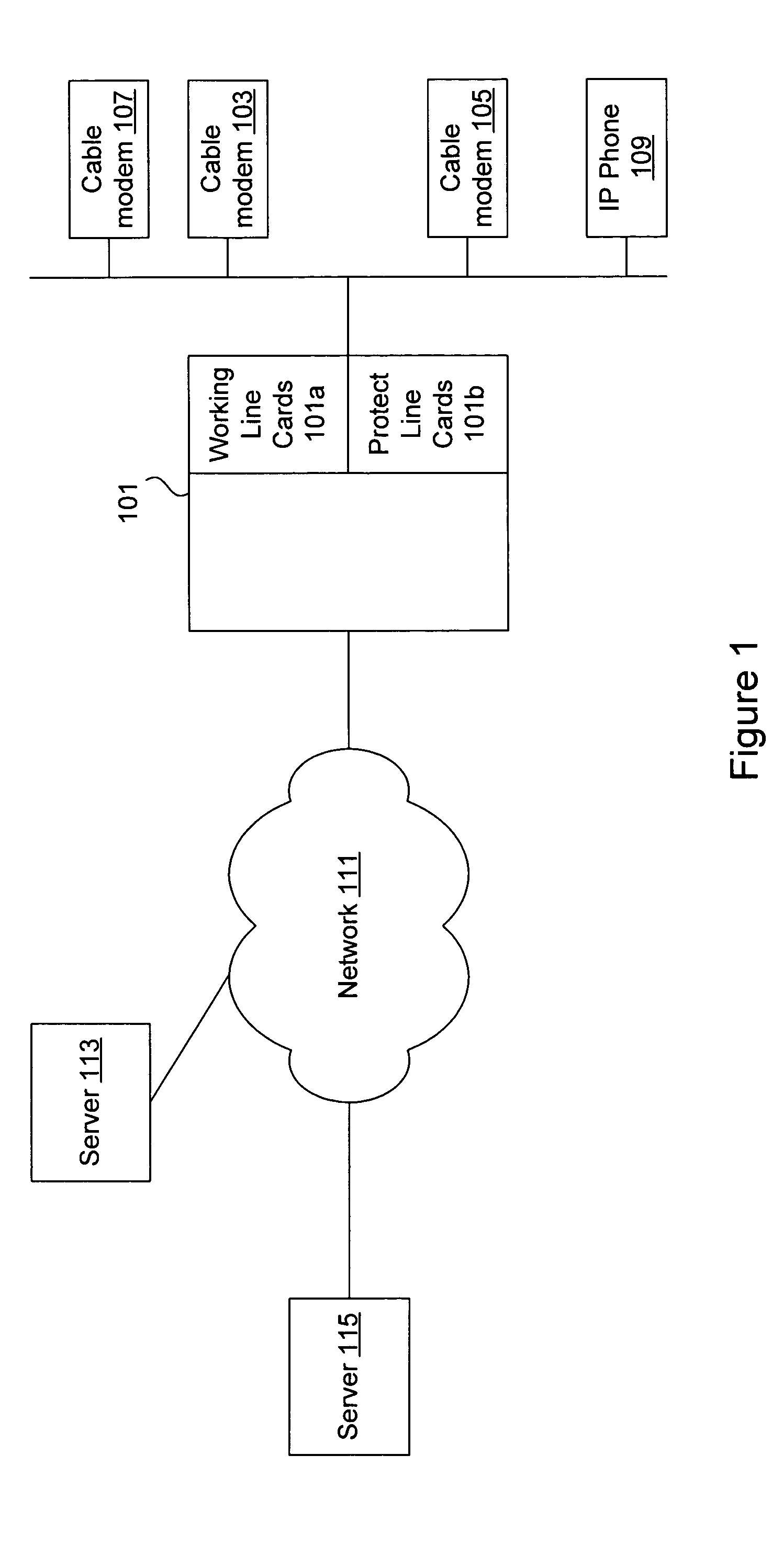
[0022]FIG. 1 is a diagrammatic representation of a system in which the techniques of the present invention can be used. Although FIG. 1 will be used to describe the present invention in the context of cable modems, it should be noted that the techniques of the present invention are general and can be applied in a variety of contexts. A cable network headend 101 couples ...


PUM


Abstract

According to the present invention, methods and apparatus are provided to allow efficient switching of cable lines from failed line cards to protect line cards. Line cards may be arranged in multiple protect and active groups supporting both upstream and downstream transmission frequencies. A combined electromechanical and solid state switching fabric is provided to efficiently allow reassignment of cable lines to line cards.

Description

BACKGROUND OF THE INVENTION[0001]1. Field of the Invention[0002]The present invention generally relates to network switching. More specifically, the present invention provides techniques for effectively and efficiently switching cable lines to available active line cards.[0003]2. Description of Related Art[0004]A cable network headend such as a cable modem termination system typically includes multiple line cards connected to various cable lines. The cable lines may be coaxial cable lines or fibre optic lines connected to cable plants and cable networks. Since a variety of reasons can cause line card failure, mechanisms are often provided to support high availability and redundancy by providing redundant line cards.[0005]In some examples, protect line cards are provided along with active line cards. For example, there may be one protect line card associated with five active line cards. If an active line card connected to a cable line fails, the cable line is switched over onto a pro...

Claims


Application Information

Patent Timeline
Patent Type & Authority Patents(United States)
IPC IPC(8): H04J1/16H04J3/14H04L12/28
CPCH04L12/2854
Inventor ZHOU, JIAHUAIMELLER, RICK
Owner CISCO TECH INC
Why Eureka
Try Eureka