
Gas chromatography system architecture

a technology of gas chromatography and system architecture, which is applied in the field of gas chromatography systems, can solve the problems of increasing the design constraints of a system suitable for down-hole operation, increasing the design constraints of a system, and requiring a relatively large supply of carrier gas, so as to facilitate thermal management and improve the operability and reliability of gas chromatographic analysis.

Inactive Publication Date: 2009-10-13
SCHLUMBERGER TECH CORP
View PDF14 Cites 19 Cited by
  • Summary
  • Abstract
  • Description
  • Claims
  • Application Information

AI Technical Summary

Benefits of technology

The system enables reliable and efficient chromatographic analysis in down-hole environments by reducing carrier gas consumption, facilitating thermal management, and providing a compact, self-contained solution with on-board waste disposal, suitable for various challenging environments.

Problems solved by technology

Conventional gas chromatography apparatus is built around a standard chromatographic column and injector which, when packaged with thermal management apparatus, becomes bulky.
As a result, for conventional systems, a relatively large supply of carrier gas is needed.
In addition, vibrations and typically high temperature (about 200 degrees Celsius) and high pressure environments are experienced down-hole, adding further constraints to the design of a system suitable for down-hole operation.
Furthermore, the temperature of components of a chromatogram should be controlled and monitored accurately, which is difficult in a down-hole environment.
Thus, given the space and other constraints of down-hole environments, the use of traditional gas chromatography devices down-hole would be challenging.
However, none have been designed for down-hole applications.
However, the SLS device lacks the inclusion of high-pressure sampling and thermal management requirements to operate in a high temperature (e.g., about 200° C.) down-hole environment.
The SLS unit also lacks an on-board supply of carrier gas and means of waste disposal that would be desirable, or even necessary, for down-hole applications.
Furthermore, the SLS system uses a glued component layout consisting of fused silica tubes to provide fluidic inter-connections which may not be suitable for high-temperature environments.
The injector, although micro-scale, needs an external supply of regulated fluidic pressure to operate various micro-valves and is not designed to operate in a high temperature and pressure environment.
The fluidic connections are achieved by glued capillary tubes which may be unsuitable for down-hole applications or other high temperature environments.
In addition, the C2V unit does not include an on-board supply of carrier gas and waste disposal is not addressed.

Method used


Image

  • Gas chromatography system architecture
  • Gas chromatography system architecture
  • Gas chromatography system architecture

Examples


Embodiment Construction

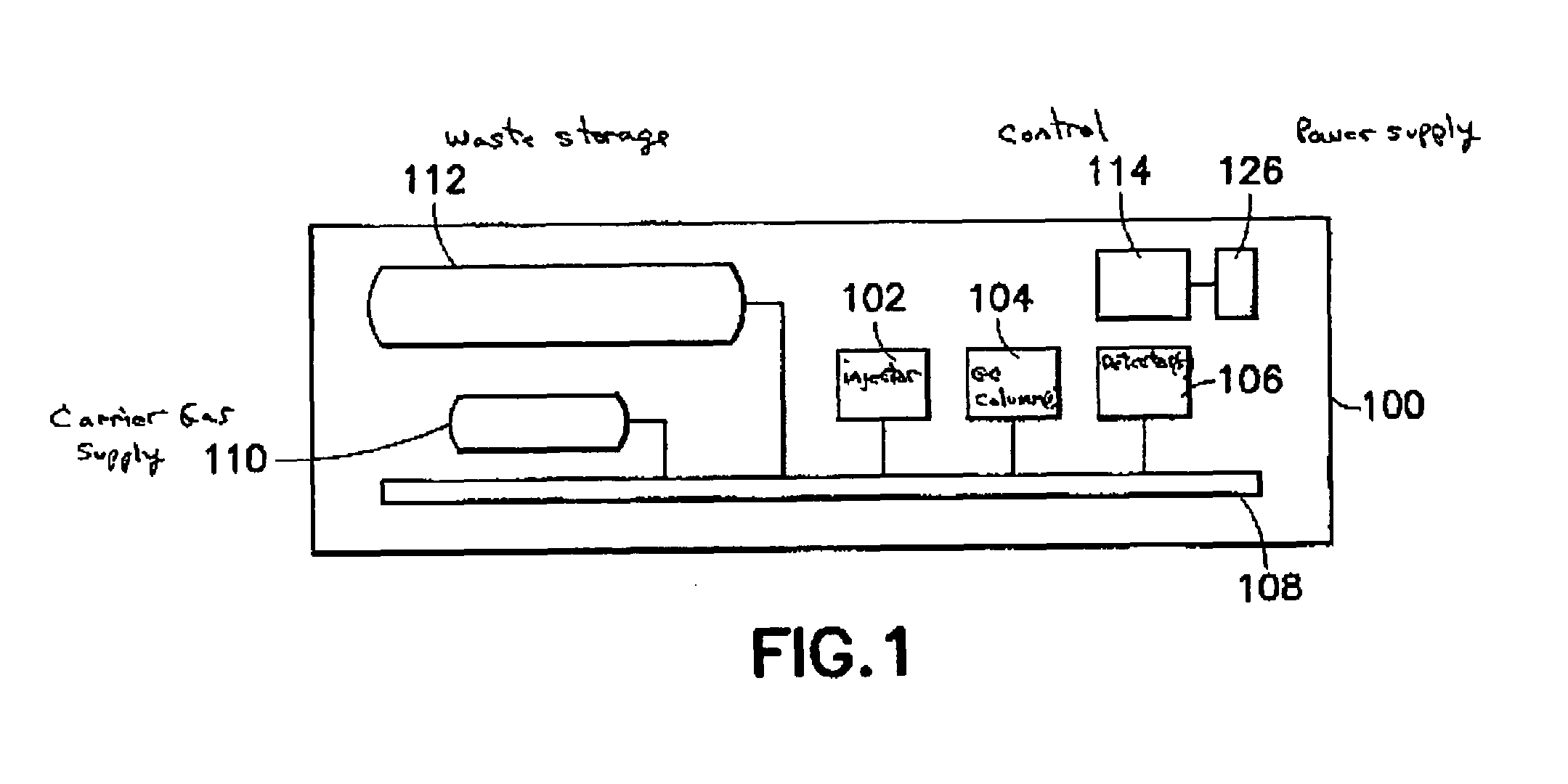
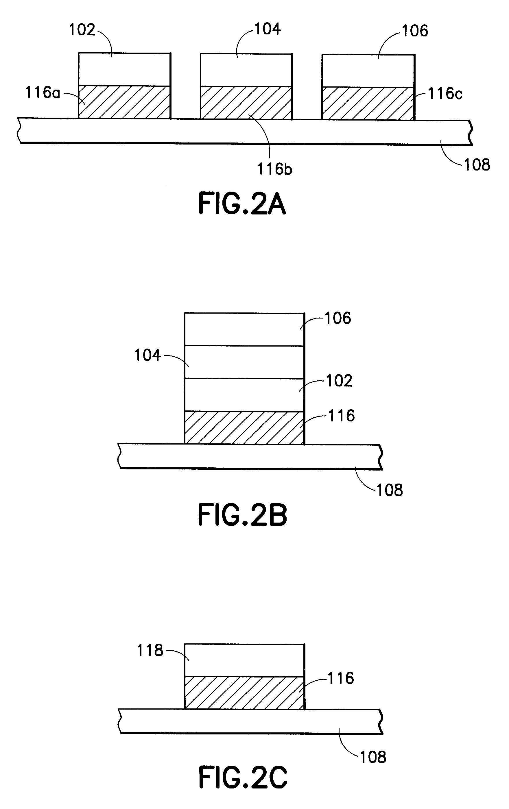
[0025]Embodiments of the invention and aspects thereof are directed to a gas chromatography apparatus and system that incorporates micro-scale components and may be suitable for use in a variety of environments. Traditionally, gas chromatographic analysis is performed on the surface of the earth, usually in a laboratory or similar environment. A sample may be collected at a remote location or sample site, for example, an underground or underwater location, and then returned to a testing facility, such as a laboratory, for chromatographic analysis. As discussed above, although there have been some developments of portable gas chromatography systems, none have been suitable for down-hole applications. Therefore, to address these and other limitations in the prior art, aspects and embodiments of the invention are directed to a gas chromatography system having an architecture that allows for down-hole operation. For example, boreholes are typically small diameter holes having a diameter...


PUM

PropertyMeasurementUnit
inner diameteraaaaaaaaaa
diametersaaaaaaaaaa
temperatureaaaaaaaaaa

Abstract

A self-contained micro-scale gas chromatography system that includes a plurality of gas chromatography components arranged on a micro-fluidic platform with nearly zero dead volume “tubeless” fluidic connections for the gas chromatography components. The micro-fluidic platform includes a plurality of flow channels that provide fluid flow paths for a sample, carrier gas and waste gas through and among the micro-fluidic platform and the plurality of gas chromatography components. The system may also include an on-board supply of carrier gas and on-board waste management, as well as a thermal management scheme making the system suitable for use in oil and gas wells and also other remote environments.

Description

BACKGROUND[0001]1. Field of Invention[0002]The present invention relates to gas chromatography systems and, more particularly, to small-scale systems that may be suitable for operation in various environments.[0003]2. Discussion of Related Art[0004]Gas chromatography uses chromatographic columns to separate molecular species within a sample fluid and thereby to extract information about the sample fluid. A chromatographic column has a stationary phase fixed inside the column and a mobile phase which is a carrier gas, such as, helium that flows through the column. The sample is collected, injected into the column and then transported by the carrier gas into and through the column. If the sample is in a liquid state, the sample may first be injected into a vaporization chamber to be vaporized then transported through the column. As a sample progresses through the column, the individual molecular components are slowed down based on their affinity to the stationary phase. At the outlet ...

Claims


Application Information

Patent Timeline
Patent Type & Authority Patents(United States)
IPC IPC(8): G01N30/04
CPCG01N30/88B01L3/502715B01L2200/18G01N30/6095G01N2030/8881G01N2030/025G01N2030/8854
Inventor SHAH, JAGDISHBOSTROM, NEIL WILLIAMCHEN, HUADAITO, SHIGEOHARRIGAN, EDWARD
Owner SCHLUMBERGER TECH CORP
Learn More