Lightweight, portable cooking stove

a portable, small technology, applied in the direction of domestic stoves or ranges, gaseous heating fuel, combustion types, etc., can solve the problems of limited popularity of alcohol-fueled stoves in the united states, poor overall performance, etc., to prevent the uneven distribution of heat, convenient, safe and simple, and convenient to operate

Inactive Publication Date: 2009-10-13
HUGGINS TIMOTHY G
View PDF51 Cites 11 Cited by
  • Summary
  • Abstract
  • Description
  • Claims
  • Application Information

AI Technical Summary

Benefits of technology

[0008]It is an objective of this invention to achieve a high heat output and stable cooking performance suitable for fast and effective cooking in a variety of outdoor conditions of the wind and weather—attaining overall cooking performance which consistently meets or exceeds the performance of petroleum-fueled stoves.
[0035]All the components of the current invention nest together when packed, forming a single, compact unit in the shape of a hollow cylinder. This cylinder is proportioned to also contain a fuel bottle, whereby the entire invention is rendered conveniently portable in a sturdy and compact package that weighs only a few ounces and can be comfortably held in the palm of the hand. This package is so efficient that when the fuel bottle is filled with fuel, less than ten percent of the package contains empty space. Being so contained in a single, integrated unit, all of the components are protected from loss of damage, and the stove can be quickly unpacked and set up for use.

Problems solved by technology

However, in the United States they have had limited popularity.
This limited popularity is primarily due to two factors.
The first factor that has limited the popularity of alcohol-fueled stoves in the United States is their overall poor performance.
In real outdoor conditions of wind and weather, these stoves rapidly become incapable of cooking a meal.
These stoves demonstrate a variety of forms and features that cause inefficient performance and wasted heat.
The overall inefficient performance of alcohol stoves known to prior art also causes an excessive consumption of fuel.
This is undesirable both due to the increased cost of operating the stove, as well as the increased weight of fuel that must be carried.
The second factor that has limited the popularity of alcohol-fueled stoves in the United States is the inability to effectively adjust the heat output of the stove.
Often these stoves provide no manner of heat adjustment.
Positioning or adjusting of the snuffer can be a rather awkward undertaking and requires removing the cooking pot or reaching under it.
This presents a danger of burning or scalding.
Obstructing the flame in this way tends to produce a small hot spot on the bottom of the cooking pan and prevents the even distribution of heat for thorough and rapid cooking.
In summation, the two primary factors that have limited the popularity of alcohol stoves in the United States are their overall poor performance and the inconvenience with which the heat adjustment is effected.
The disadvantages include the need for bulky and heavy metal fuel containers, high operating cost, poor operation in wind or cold weather, need to constantly tend them during cooking, odor, danger of fuel spills, complexity, poor reliability, the need to carry maintenance kits, and the possibility of dangerous flare-ups when lighting the stove.

Method used


Image

  • Lightweight, portable cooking stove
  • Lightweight, portable cooking stove
  • Lightweight, portable cooking stove

Examples


embodiment 104

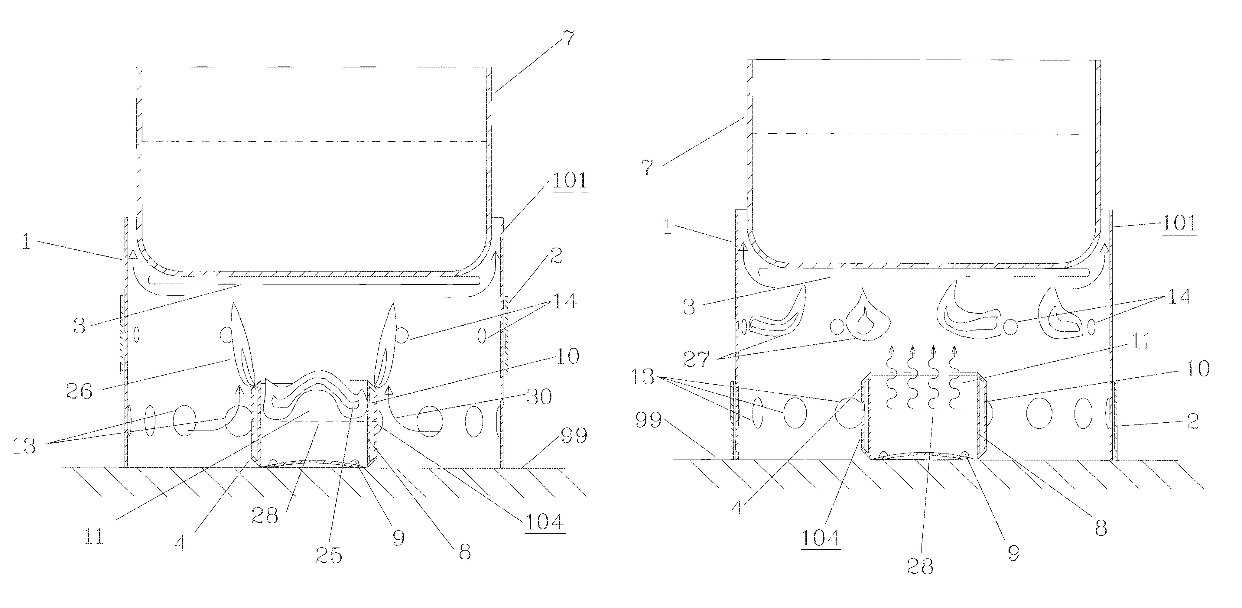
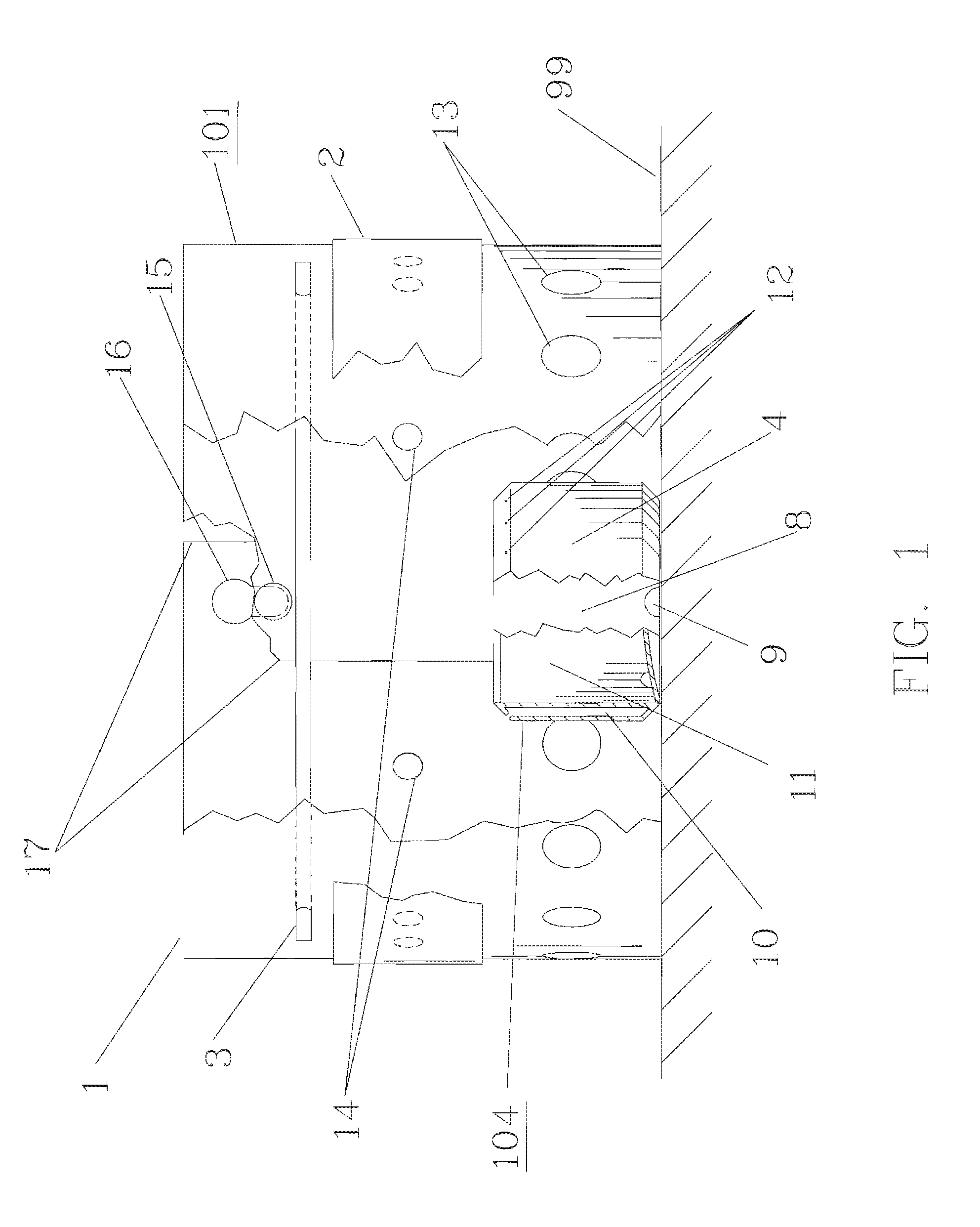
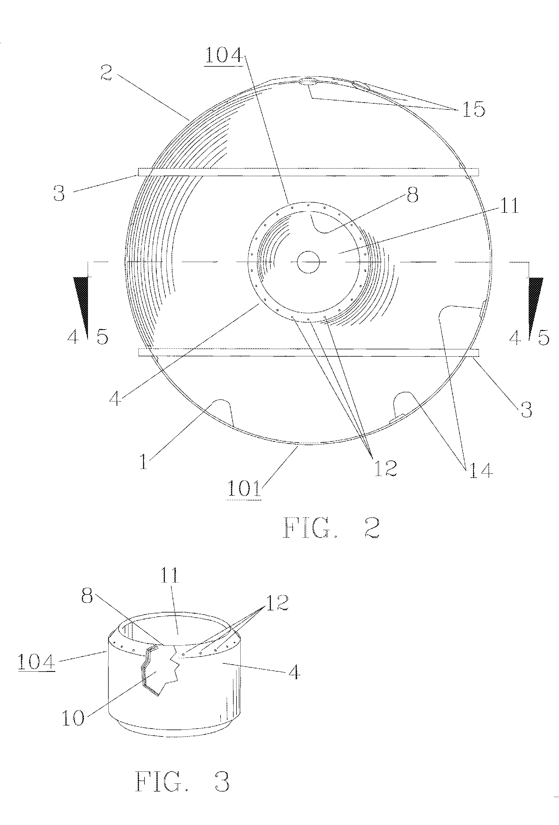
[0089]FIG. 8 shows a plan view of an alternate embodiment of the fuel vaporizer 131. FIG. 9 shows a cutaway elevation view of this alternate embodiment fuel vaporizer 131, and FIG. 10 shows a perspective view. The alternate embodiment of the fuel vaporizer 131 is adapted to concentrate a large amount of heat on a small, confined chamber 34. The alternate embodiment fuel vaporizer 131 also surrounds and envelopes this small, confined chamber 34 in such a way that very little heat can escape from it. In this way the alternate embodiment of the fuel vaporizer 131 is capable of achieving a high rate of fuel vaporization with the concatenate effect of a high overall heat output for the stove. The alternate embodiment fuel vaporizer 131 is potentially capable of even greater heat output than the preferred embodiment 104 of the fuel vaporizer.

[0090]The alternate embodiment of the fuel vaporizer 131 comprises a vessel in the shape of a shallow, cylindrical cup 31. This shallow, cylindrical ...

embodiment 140

[0100]FIG. 15 shows a perspective view of an alternate embodiment of the fuel vaporizer 140. FIG. 16 shows a cutaway, sectional elevation view of this alternate embodiment 140. The alternate embodiment of the fuel vaporizer 140 is provided with cylindrical duct 53 coaxial with the body of the fuel vaporizer. This cylindrical duct 53 extends thru the center of the fuel vaporizer 140. This cylindrical duct 53 is adapted to provide a source of combustion air to the center of the fuel vaporizer 140. By providing combustion air to the center of the fuel vaporizer 140, complete combustion of the vaporized fuel can be effected.

[0101]The alternate embodiment 140 shares various features with the alternate embodiment 131 of the fuel vaporizer, and operates in a similar manner. The alternate embodiment of the fuel vaporizer 140 comprises a vessel in the shape of a shallow, cylindrical cup 49. This shallow, cylindrical cup 49 incorporates a double wall 50. By means of this double wall 50 the in...

embodiment 180

[0106]FIG. 29 shows a plan view of an alternate embodiment of the fuel vaporizer 180. FIG 30 shows a cutaway, sectional elevation view of this alternate embodiment 180. The alternate embodiment 180 shares various features with the alternate embodiments 140 and 145 of the fuel vaporizer, and operates in a similar manner. The alternate embodiment of the fuel vaporizer 180 is provided with cylindrical duct 97 coaxial with the body of the fuel vaporizer. This cylindrical duct 97 extends thru the center of the fuel vaporizer 180. This cylindrical duct 97 is adapted to provide a source of combustion air to the center of the fuel vaporizer 180. By providing combustion air to the center of the fuel vaporizer 180, complete combustion of the vaporized fuel can be effected.

[0107]The alternate embodiment of the fuel vaporizer 180 comprises a vessel in the shape of a shallow, cylindrical cup 91. This shallow, cylindrical cup 91 comprises a double wall 98. By means of this double wall 98 the inte...


PUM


Abstract

A small, lightweight, portable cooking stove that utilizes alcohol as fuel and is suitable for backpacking, hunting, camping and similar activities. The cooking stove includes a combustion chamber which encloses, contains and regulates the entire combustion process. The stove also includes an efficient fuel vaporizer, which is adapted to perform in unison with the combustion chamber, to effect the metered and efficient mixing of the air and fuel vapor. An integral, simple and convenient means is provided to vary the intensity and pattern of the heat output, thereby controlling the cooking performance of the stove. The stove achieves high heat output and efficiency, low fuel consumption, and superior cooking performance in a small, lightweight, portable, convenient, simple and integrated assembly.

Description

CROSS-REFERENCE TO RELATED APPLICATION[0001]This application is a continuation-in-part patent application of application Ser. No. 10 / 951,128 filed Sep. 27, 2004, now U.S. Pat. No. 7,246,614, the entire contents of which are incorporated herein by reference.TECHNICAL FIELD[0002]The invention is a small, lightweight, portable cooking stove that uses alcohol as fuel.BACKGROUND AND SUMMARY OF THE INVENTIONPrior Art[0003]Portable cooking stoves designed to use alcohol as a fuel are well known to prior art. These are used by hikers, campers, backpackers, hunters and others who have a need to boil water or cook a hot meal in remote locations or primitive conditions. As a fuel, alcohol has various advantages over petroleum based fuels. Alcohol is widely available, inexpensive, convenient, relatively innocuous and easy to handle. It can be readily repackaged and safely carried in lightweight plastic bottles. Alcohol stoves are typically smaller and lighter than petroleum-fueled stoves. Alcoh...

Claims


Application Information

Patent Timeline
Patent Type & Authority Patents(United States)
IPC IPC(8): F23D5/04F23D5/12F23D5/18F24C5/02
CPCA47J36/26F24C5/20F24C5/02
Inventor HUGGINS, TIMOTHY G.
Owner HUGGINS TIMOTHY G
Why Eureka
Try Eureka