
Cam action tightening receiver hitch assembly

a receiver and hitch technology, applied in the field of adapters, can solve the problems of equipment being carried to repeatedly bang into the vehicle, damage the vehicle or the equipment being carried, and tools and skills not available, so as to eliminate wobble and rattle, reduce labor intensity, and reduce labor intensity.

Inactive Publication Date: 2009-10-13
SPEER WILLIAM W +1
View PDF27 Cites 37 Cited by
  • Summary
  • Abstract
  • Description
  • Claims
  • Application Information

AI Technical Summary

Benefits of technology

"The present invention provides a hitch adapter that can securely attach a variety of hitch accessories to a vehicle's receiver hitch. The adapter includes an inner square tube for Class-II 1.25\" drawbars and an outer U-channel for Class-III 2\" receivers. The inner square tube and outer U-channel are welded together to eliminate any movement between the accessory and the hitch. The adapter can be retrofit to existing accessories and includes a threaded pin for securing the accessory in the hitch. The invention provides a simple and cost-effective solution to eliminate wobble, wear, and noise in the hitch accessory assembly."

Problems solved by technology

Having two differently sized systems in widespread use, of course, causes fitment problems.
Many prior art adapters and converters are available, but they universally provide sloppy fits between parts that can rattle and allow the accessories to wobble and move.
Sometimes this movement can allow the equipment being carried to repeatedly bang into the vehicle and damage the vehicle or the equipment being carried.
Some prior art adapters have attempted various kinds of wedges and bolt arrangement to take up slack, but these often require tools and skills not available, and the nature of the mating parts causes the accessories to angle inappropriately away from normal.
Furthermore, prior art adapters have not provided multi-axis tightening and stabilization.

Method used


Image

  • Cam action tightening receiver hitch assembly
  • Cam action tightening receiver hitch assembly
  • Cam action tightening receiver hitch assembly

Examples


Embodiment Construction

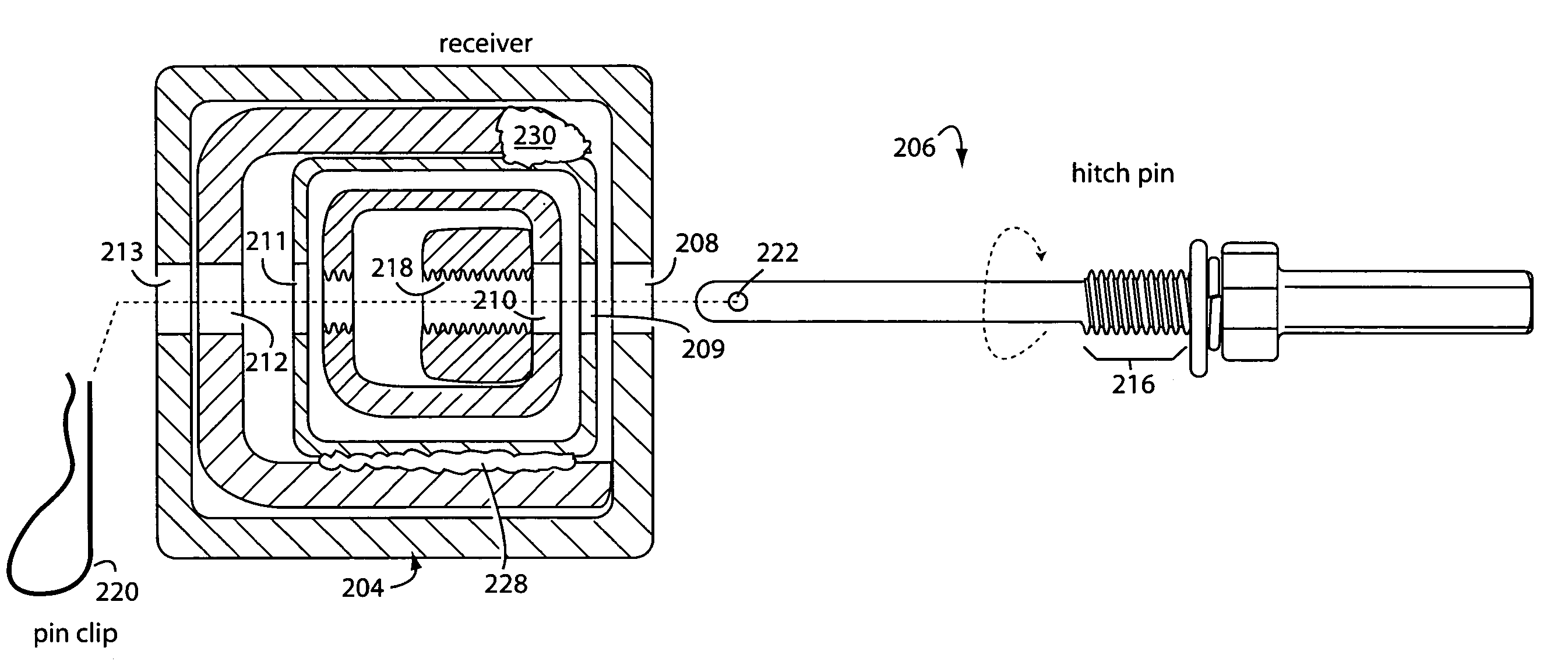
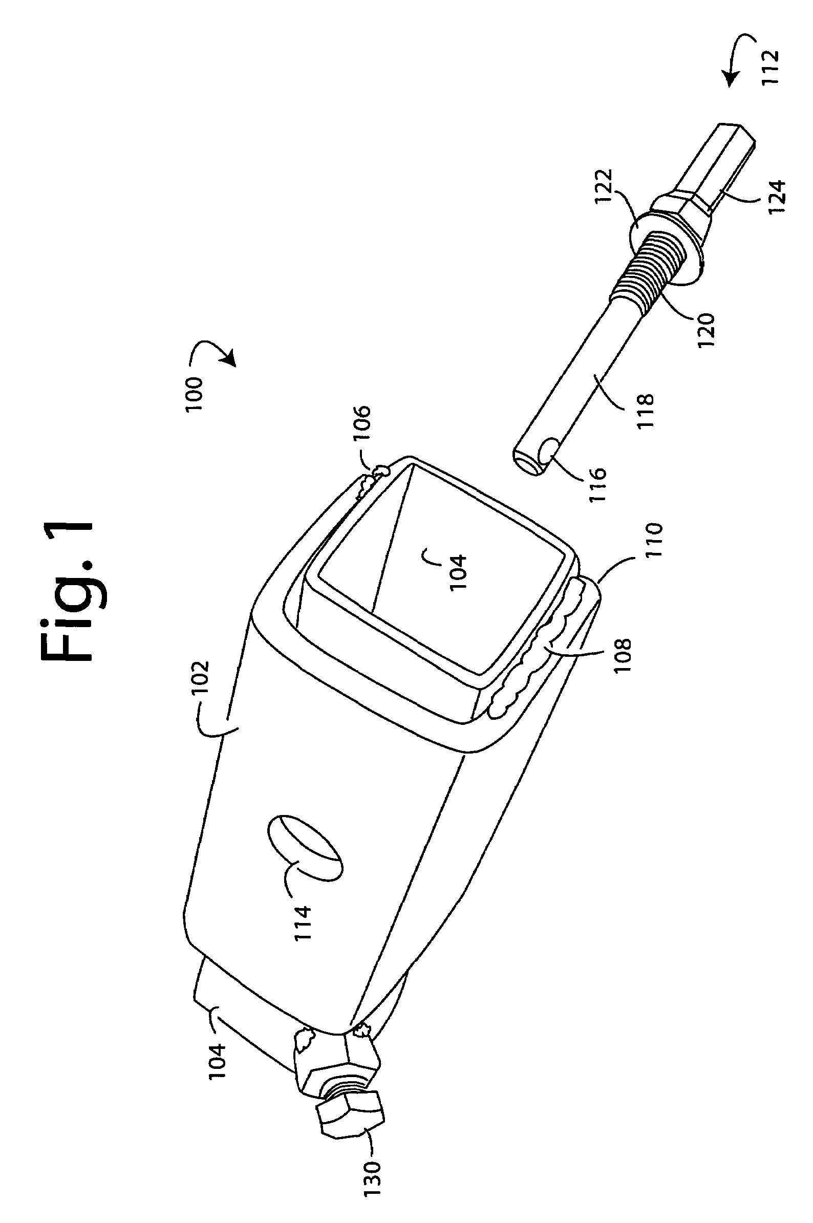
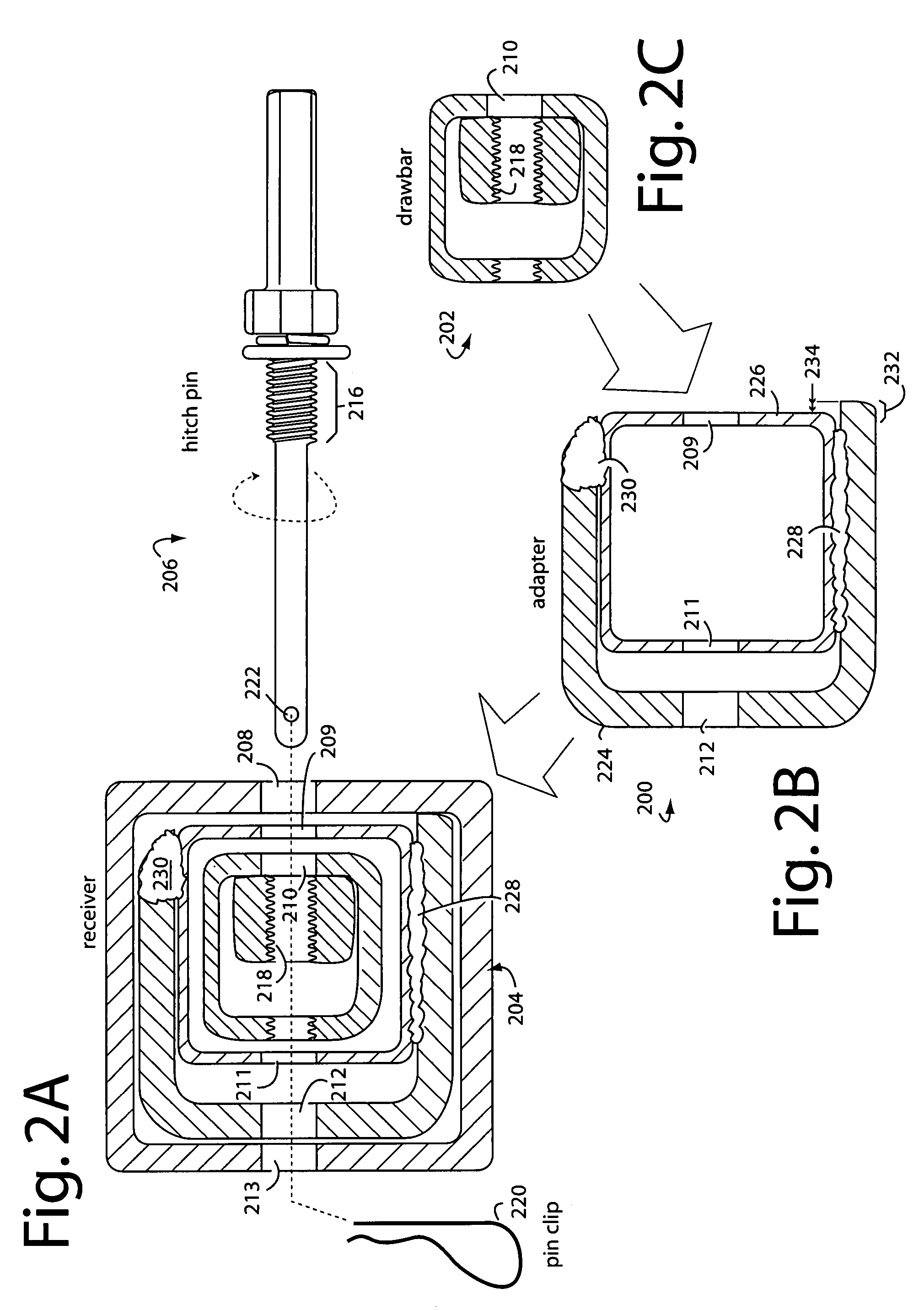
[0016]FIG. 1 represents a hitch adapter embodiment of the present invention, and is referred to herein by the general reference numeral 100. The hitch adapter 100 allows a Class-II 1.25″ drawbar to be secured within a Class-III 2″ receiver. It comprises a U-channel 102 of mild steel 0.25″ thick and typically formed with outside cross-section of just under 2″ square and a length of 4.5″. The U-channel 102 is welded to an inner square tube 104 by short welds represented by welds 106 and 108. Importantly, a longer leg 110 of U-channel 102 is formed and welded such that it protrudes about 0.0675″ along its longitudinal length past the adjacent outside corner of inner square tube 104. This detail is shown more fully in FIG. 2.

[0017]The most common receiver pins are ½″ and ⅝″ in diameter. Class-II receiver hitches have 1¼″ receptacles and use ½″ pins. Class-III and Class-IV receiver hitches have 2″ receptacles and use ⅝″ pins.

[0018]A hitch pin 112, or other type fastener capable of snuggi...


PUM


Abstract

A hitch adapter comprises an inner square tube member for receiving Class-II 1.25″ drawbars and an outer U-channel member for plugging into a Class-III 2″ receiver. The inner square tube and outer U-channel members are welded together such that one wall of the inner square tube bridges the gap between the distal edges on opposite legs of the outer U-channel. One such leg of the outer U-channel is longer than the other and is positioned and aligned to protrude about 1 / 16″ beyond the adjacent outer corner of the inner square tube member. Such protrusion nests into the respective inside corner of the particular Class-III 2″ receiver it is mated to. The protrusion provides a camming action to take up any looseness and slack, and thereby eliminate wobble and rattle when installed by a user. A series of hitch pin holes allows a threaded hitch pin to pass through the adapter, a Class-II 1.25″ drawbar and a Class-III 2″ receiver. Threads inside the Class-II 1.25″ drawbar engage the hitch pin threads and provide the user a way to secure the whole assembly.

Description

1. FIELD OF THE INVENTION[0001]The present invention relates to adapters to fit Class II hitch accessories in Class III receivers, and more particularly to devices that take up the slack and wobble in such adapters so they will be suitable to carry bicycles on receiver carriers.2. DESCRIPTION OF THE PRIOR ART[0002]Two of the most popular towing hitches in widespread use on cars and highways in America are the so-called Class-II and Class-III systems. Both are very familiar to the average American, the Class-II system uses drawbars with 1.25″ square cross sections that plug into matching receivers and that are secured with a pin. Such are rated for no more than 3500 pounds gross towing weight and 300 pounds tongue weight. The Class-III system ups those ratings to 5000 pounds gross towing weight, and 500 pounds tongue weight. Class-III drawbars are 2.0″ square in cross section and the receivers are sized to match. What the vehicle is actually rated for can be less than what the drawba...

Claims


Application Information

Patent Timeline
Patent Type & Authority Patents(United States)
IPC IPC(8): B60D1/04B60D1/155E04B9/16
CPCB60D1/155B60D1/58B60D1/52Y10T403/7117
Inventor SPEER, WILLIAM W.SPEER, W. LOUIS
Owner SPEER WILLIAM W
Learn More