Non-contact thermal platforms

a technology of non-contact support and support plate, which is applied in the direction of gripping head, chemical vapor deposition coating, application, etc., can solve the problems of backside contamination and/or scratches, non-homogeneous heating or cooling of wafers,

Active Publication Date: 2009-10-13
COREFLOW SCI SOLUTIONS
View PDF11 Cites 62 Cited by
  • Summary
  • Abstract
  • Description
  • Claims
  • Application Information

AI Technical Summary

Benefits of technology

[0011]FIG. 1 is a schematic, cross-section illustration of a non-contact thermal system including a thermal platform configuration, according to an exemplary embodiment of the invention;
[0012]FIG. 2 is a schematic illustration of a graph depicting a change in the temperature of a wafer versus time, in accordance with exemplary embodiments of the invention;
[0013]FIG. 3 is a schematic, top-view illustration of a vacuum preloaded (PV-type) non-contact support arrangement, in accordance with some exemplary embodiments of the invention;
[0014]FIG. 4 is a schematic, cross-section illustration of a thermal platform configuration according to another exemplary embodiment of the invention;
[0015]FIG. 5 is a schematic cross-section illustration of a thermal platform configuration according to yet another exemplary embodiment of the invention;
[0016]FIG. 6 is a schematic, illustration of a non-contact thermal system, in accordance with another exemplary embodiment of the invention;
[0017]FIGS. 7a and 7b are schematic illustrations of temperature versus vertical location in the system of FIG. 6;
[0018]FIG. 8 is a schematic illustration of a fluid-cushion thermal insulation arrangement according to some exemplary embodiments of the invention;
[0019]FIG. 9 is a schematic illustration of a multi-chamber non-contact thermal system, in accordance with some exemplary embodiments of the invention; and
[0020]FIGS. 10a-10c are schematic illustrations of three, respective, in line non-contact thermal systems according to some exemplary embodiments of the invention.
[0021]FIGS. 11a-11b are schematic illustrations of optional local thermal treatment where the object is stationary.
[0022]FIGS. 12a-12e are schematic illustrations of optional circular thermal treatment apparatuses

Problems solved by technology

Thus, since increasing / decreasing the temperature of the chuck may require a relatively long time period, it may be required to use several pre-heated chucks in a process requiring applying different temperatures to the wafer.
Irregularities on the surface of the wafer being in contact with the chuck may also result in non-homogeneous heating or cooling of the wafer.
Furthermore, the contact between the wafer and the chuck may result in damages, e.g., backside contamination and / or Electro Static Damage (ESD) to the wafer.
Slippage between the wafer and the chuck, resulting in backside contamination and / or scratches, may occur due to thermal expansion or contraction of wafer during heating or cooling.

Method used


Image

  • Non-contact thermal platforms
  • Non-contact thermal platforms
  • Non-contact thermal platforms

Examples


Embodiment Construction

[0024]In the following detailed description, numerous specific details are set forth in order to provide a thorough understanding of the invention. However, it will be understood by those of ordinary skill in the art that the present invention may be practiced without these specific details. In other instances, well-known methods, procedures, components and circuits have not been described in detail so as not to obscure the present invention.

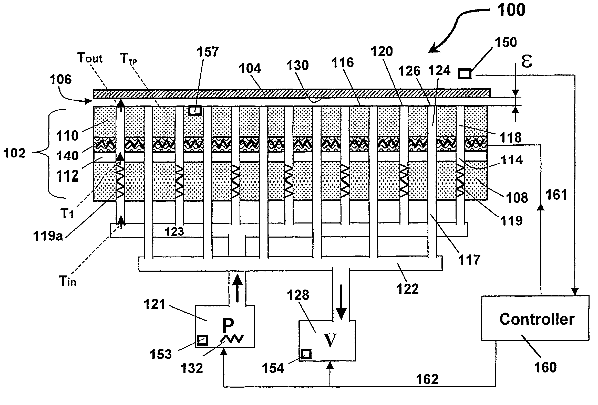
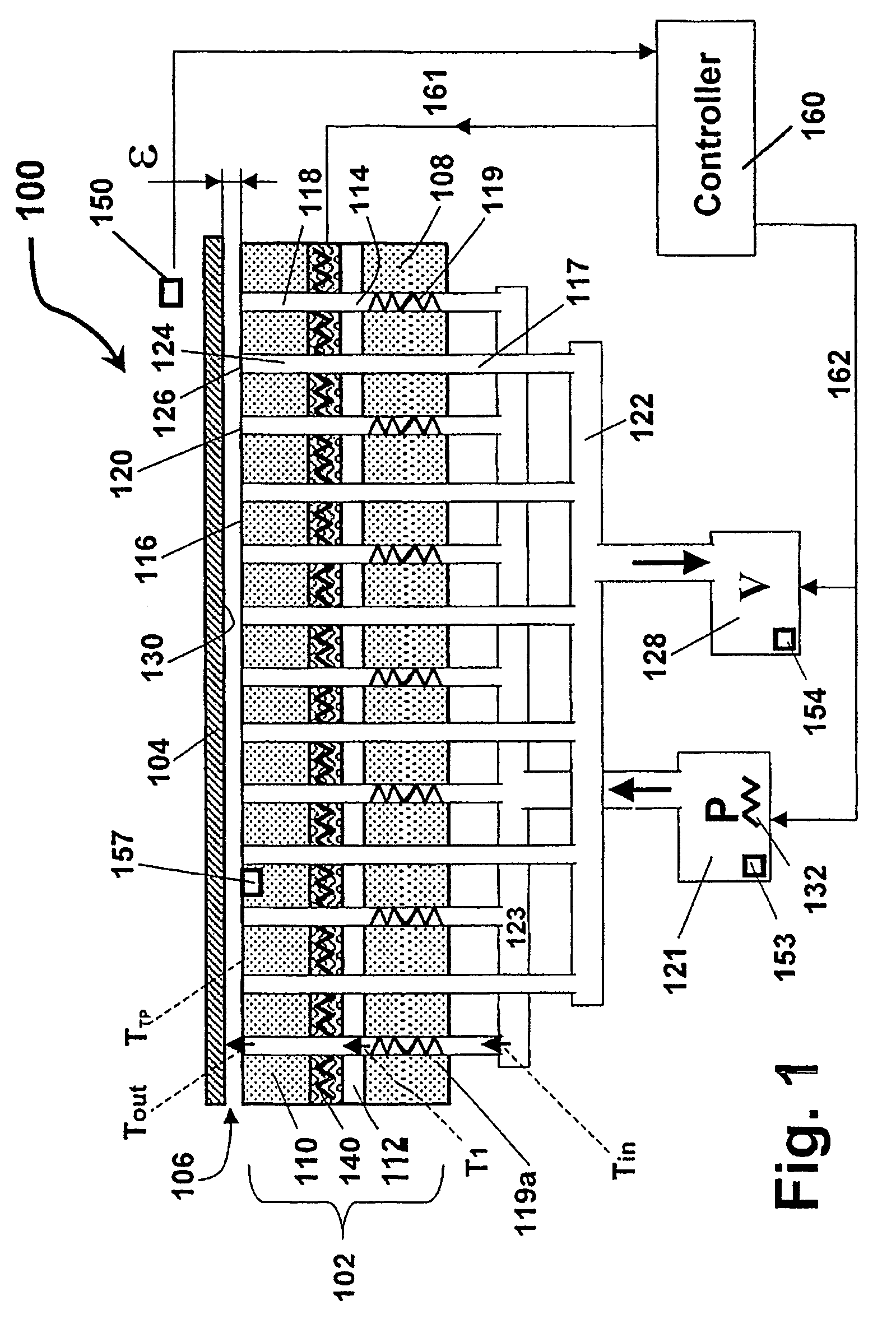
[0025]Embodiments of the present invention provide a device, system and method for heating / cooling an object, e.g., a Semi-Conductor (SC) wafer, while the object is supported by a non-contact support platform, which is adapted to support the object without contact, for example, by fluid-cushion induced forces, as described below.

[0026]It is appreciated that for the purpose of the present invention the term “supporting” may also mean “clamping” (hereinafter referred to as: “supporting” or “clamping”), depending on the relevant context.

[0027]Signi...


PUM

PropertyMeasurementUnit
distanceaaaaaaaaaa
distanceaaaaaaaaaa
distanceaaaaaaaaaa

Abstract

A thermal treatment system comprising at least one apparatus for thermally treating an object, the apparatus comprising: one platform or two substantially opposite platforms, where at least one of the platforms has at least one thermal means for heating or cooling of the object; and at least one of the platforms has fluid-mechanical means for supporting the object without contact. The platform has an active surface comprising at least one of a plurality of basic cells, each basic cell having at least one of a plurality of pressure outlets and at least one of a plurality of fluid-evacuation channels. At least one of the pressure outlets of each basic cell is fluidically connected through a flow restrictor to a high-pressure fluid supply, the pressure outlets providing pressurized fluid for maintaining a fluid-cushion between the object and the active-surface of the platform. The flow restrictor characteristically exhibits fluidic return spring behavior. Each of the evacuation channels has an inlet and outlet, for locally balancing mass flow for the basic cells.

Description

CROSS-REFERENCE TO RELATED APPLICATIONS[0001]This application is a National Phase Application of PCT International Application No. PCT / IL2005 / 000299, entitled “Non-Contact Thermal Platforms”, International Filing Date Mar. 16, 2005, published on Sep. 22, 2005 as International Publication Number WO 2005 / 086588; which in turn claims priority from U.S. Provisional Patent Application No. 60 / 553,546, filed on Mar. 17, 2004, both of which are incorporated herein by reference in their entirety.FIELD OF THE INVENTION[0002]The invention relates to Thermal-treatment apparatus and method, and to non-contact support platforms.BACKGROUND OF THE INVENTION[0003]A Semi-Conductor (SC) wafer may be heated or cooled, for example, as part of a deposition process, a baking process, or a thermal degas process, as are known in the art. Similar processes are applied at the FPD (Flat Panel Display) manufacturing lines. However such a thermal-treatment examples are not limited to the Wafers or the FPD substr...

Claims


Application Information

Patent Timeline
Patent Type & Authority Patents(United States)
IPC IPC(8): B05B1/24A47J45/00B65G25/00C23C16/00
CPCH01L21/00H01L21/6838H01L21/68714H01L21/67098H01L21/683H01L21/687
Inventor YASSOUR, YUVALHARNIK, ARIERICHMAN, HILEL
Owner COREFLOW SCI SOLUTIONS
Why Eureka
Try Eureka