Method to test routed networks

a routing resource and network technology, applied in the field of routing resource testing, can solve the problems of difficult testing of routing resources, impracticality of complex and time-consuming test procedures, etc., and achieve the effect of convenient testing, convenient testing, and convenient testing of the first portion

Active Publication Date: 2009-10-13
XILINX INC
View PDF8 Cites 5 Cited by
  • Summary
  • Abstract
  • Description
  • Claims
  • Application Information

AI Technical Summary

Benefits of technology

[0007]Embodiments of the present invention provide a system for testing routing resources between nodes in a network that use simpler structures than more complex IP modules to form source and load nodes to test the routing resources. Further, to avoid use of challenging control and observation points that may not easily allow transmission of signal patterns between a source and load, the network is broken into easier to test subnetworks to allow all routing resources to be easily tested.
[0008]For testing of routing resources, when complex IP modules are to be programmed to form the nodes, the more complex modules can be initially replaced by pattern generator modules such as FPGA slices that function to generate test patterns. The more complex modules are programmed into the FPGA after the routing resources are tested by a third party consumer, eliminating the need of a manufacturer to obtain the complex modules. In one embodiment, a module to generate patterns can be formed in an FPGA using a simple Look Up Table (LUT) and flip-flop of the slice.
[0009]Subnetworks are further created for test purposes when

Problems solved by technology

With more complex sources and loads, even after obtaining complex IP block modules, testing of the routing

Method used


Image

  • Method to test routed networks
  • Method to test routed networks
  • Method to test routed networks

Examples


Embodiment Construction

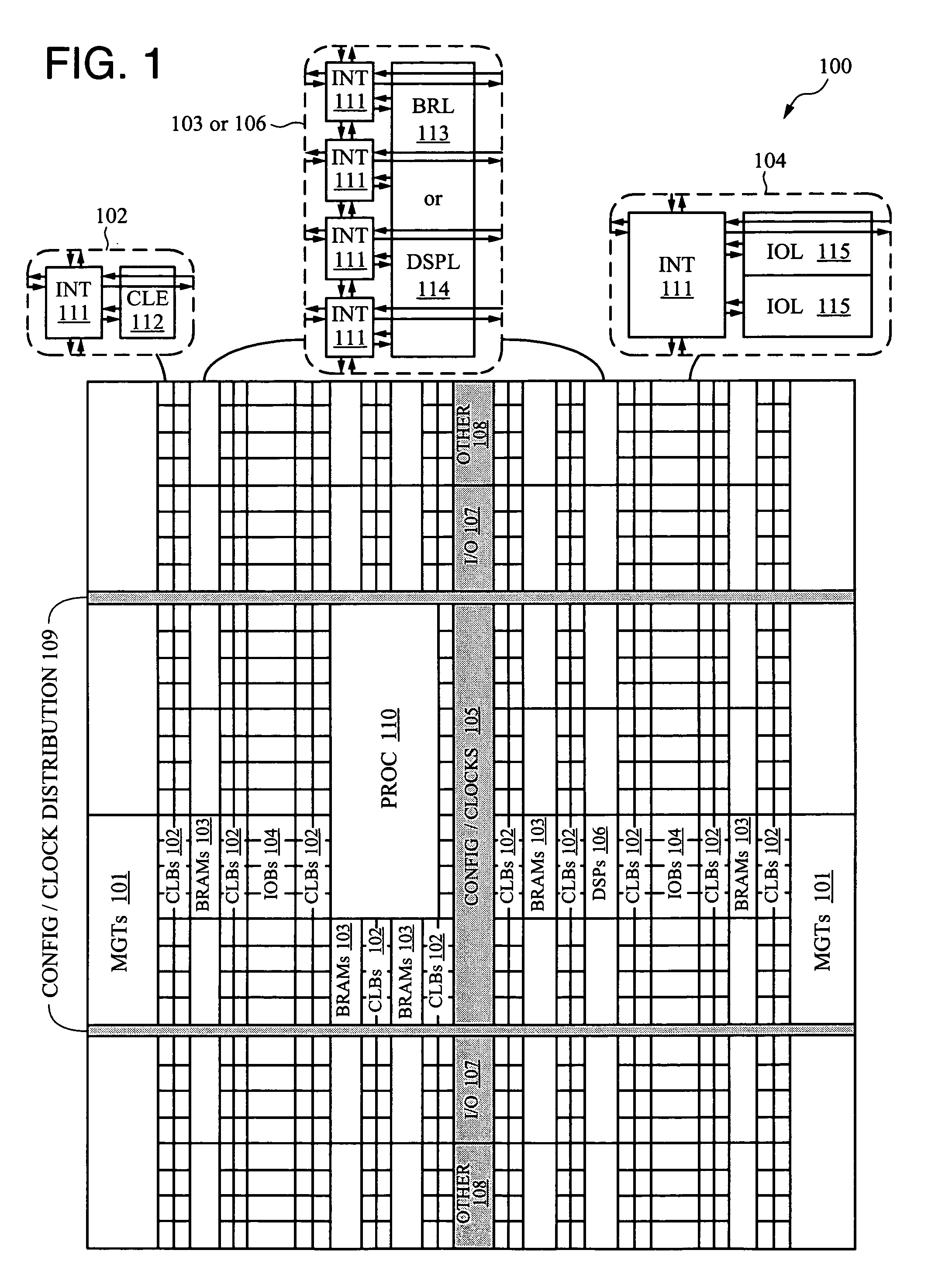
[0018]A routed network can be implemented in components of a general IC, or a more specific IC such as an FPGA. Similarly, the routed network can be provided with multiple IC components. Embodiments of the present invention can be implemented within a single IC, or using multiple ICs, whether or not the ICs include an FPGA. For convenience, however, the following description of embodiments of the present invention will be described with respect to a routed network provided within the confines of an FPGA. For reference, components provided in an FPGA are first described with respect to FIG. 1.

[0019]FIG. 1 provides an overview of typical components included in an FPGA. The components include a large number of different programmable tiles including multi-gigabit transceivers (MGTs 101), configurable logic blocks (CLBs 102), random access memory blocks (BRAMs 103), input / output blocks (IOBs 104), configuration and clocking logic (CONFIG / CLOCKS 105), digital signal processing blocks (DSP...


PUM


Abstract

Testing of routing resources in a path between network nodes is provided using simpler nodes to replace more complex IP modules which could be programmed into an FPGA after the routing resources are tested. Further, when it is impractical to generate a pattern from a source node S for testing a network path N to a load, subnetworks are created to perform testing. To provide the subnetworks, a source S′ is first provided close to node S that generates signal patterns to route through a path N′ to load L. When it is impractical to test a network path N from source to load L, a load L′ is further provided close to load L that receives the signal patterns from a routing path N″ provided from source S. The paths N′ and N″ overlap to cover all the routing resources of the path N.

Description

BACKGROUND[0001]1. Technical Field[0002]The present invention relates to testing of routing resources forming a path between a source and load(s) in a network.[0003]2. Related Art[0004]To test resources used by a network, typically a source node is configured as a pattern generator for sending signals through the network routing resource path to another node serving as a load. The patterns generated are configured to simulate all the possible operation conditions and to use all the routing resources connecting the source and load nodes to ensure that the routing resources are functioning properly.[0005]In a programmable circuit such as an FPGA, the source and load nodes can be programmed into the configurable logic blocks (CLBs) and other FPGA resources to create modules. The modules can be complicated Intellectual Property (IP) block circuits that are programmed by a customer into the FPGA after receiving the device from the manufacturer. For a manufacturer to fully test the routin...

Claims


Application Information

Patent Timeline
IPC IPC(8): G01R31/28G06F17/50G06F7/38
CPCG06F17/5077G06F17/5027G06F30/331G06F30/394
Inventor COSSOUL, MATTHIEU P. H.CHARI, MADABHUSHI V. R.
Owner XILINX INC
Why Eureka
Try Eureka