Ice chest air conditioner

a technology of air conditioner and chest, which is applied in the field of portability of air conditioners, can solve the problems of increasing the amount of space required to operate the device, system suffer from one or more, and many devices lack portability

Inactive Publication Date: 2009-10-20
CARR BOBBY LEE
View PDF27 Cites 29 Cited by
  • Summary
  • Abstract
  • Description
  • Claims
  • Application Information

AI Technical Summary

Benefits of technology

[0008]The object of the present invention is to overcome the aforementioned shortcomings in the prior art, by providing a portable, easy-to-manufacture, compact and self-contained air conditioning device.
[0012]The lid engages the body of the chest, so that the lid is held in place covering the opening when the ice chest air conditioner is in use or being transported, and so that the chest may be easily opened to access the contents. In one embodiment, when the lid and the body are engaged, the lid at least partially overlays the rim of the opening of the body and is supported thereby. Thus, the lid may overlay a part of the perimeter, or the total perimeter of the rim of the opening. In an embodiment of the invention where the lid does not overlay the total perimeter of the rim, it is nevertheless desirable that the rim of the body does not protrude above the upper surface of the lid, so, for example, the lid may be comfortably used as a seat.
[0017]Alternatively, the body of the chest may be a “soft cooler” constructed out of an insulated, flexible material, with a waterproof liner, and provided with a rigid or semi-rigid lid, that is, the lid is capable of holding its shape during operation of the invention. Typically, the lid of a soft cooler is hinged and is engaged with the body by a zipper. The “hinge” may be created by folding a continuous piece of the flexible material comprising the lid and side of the body. Preferably, the soft cooler is provided with a frame or other reinforcement, capable of maintaining the body in a free-standing position, with the lid supported a sufficient distance above the contents of the compartment, to allow air to circulate and to prevent the fan from being submerged.
[0023]The lid may be provided with a protective grate, positioned over the intake of the fan, that is, on the outer surface of the lid. The grate protects the fan and prevents injury.
[0026]The fan and vent may be positioned in the openings in the lid to achieve a substantially flat profile, relative to the outer surface of the lid. The grate for the fan can be made sufficiently strong to support weight, for example, when the fan is not in operation and the lid is used as a seat. Similarly, the vent design and materials of construction may be selected for sufficient strength to support weight. Further, the flat profile prevents damage to the fan and vent during transportation and storage of the device.
[0038]Optionally, the wire carrying electrical current from the battery pack to the fan may be run, at least for some distance, between the exterior shell and the interior shell of the chest, both for aesthetics and to avoid snagging the wire. With such a configuration it is desirable to attach the lid to the body of the chest with a hinge, thereby avoiding having to disconnect the wire when the lid is removed. Further, the wire may be run up through the wall of the chest, the hinge, and the lid, where it is connected to the fan, in such a way that the wire is not visible.

Problems solved by technology

When such inserts are used in the ice chest with a hinged lid, the lid must be propped open, which increases the amount of space required to operate the device.
The prior art systems suffer from one or more of the following shortcomings: complex construction, such as the incorporation of ductwork and passageways through the cooling (or heating) medium, or the use of a pump to circulate the cooling medium through a radiator.
Many of the devices lack portability.
The air conditioning apparatus providing an “insert” for an existing ice chest, necessarily involve an extra component, and are typically restricted in compatibility to a particular size and brand of ice chest.
Further, inserts that fit on a shelf inside the ice chest, reduce the working space within the ice chest.

Method used


Image

  • Ice chest air conditioner
  • Ice chest air conditioner
  • Ice chest air conditioner

Examples


Embodiment Construction

[0055]Without limiting the scope of the invention, a detailed description of the invention and the drawings is hereinafter set forth. All of the United States patents, which are cited in the specification, are hereby incorporated by reference.

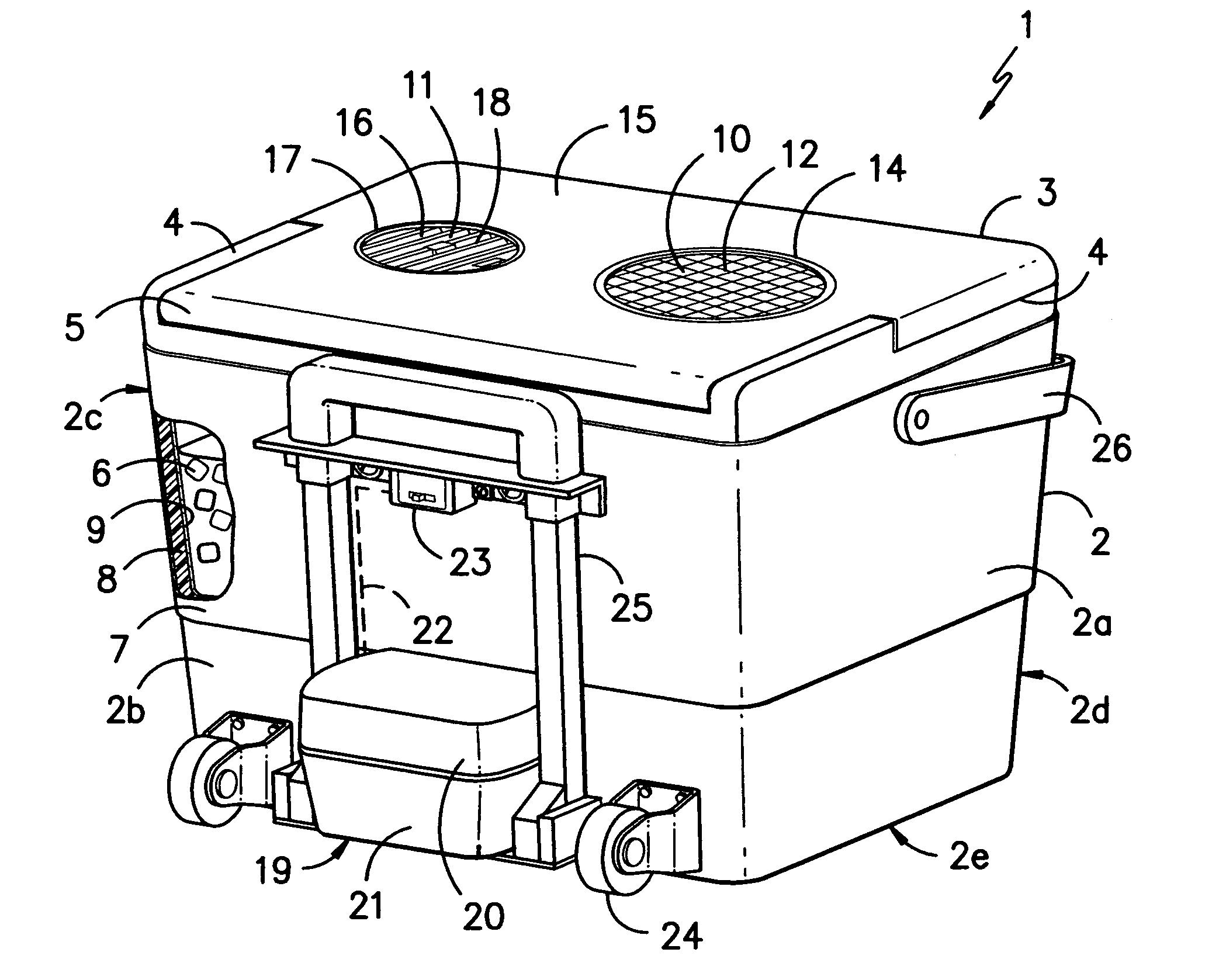
[0056]FIG. 1 is a 3-dimensional view of the back side and lid of the chest. Chest 1 is comprised of body 2 and lid 3, and has a cuboid shape. Body 2 has sides 2a-2d and bottom 2e. Body 2 has rim 4 at its upper edge. Lid 3 is attached to body 2 at rim 4 by hinges 5, which allow lid 3 to swing up, for access to the contests of the chest. Lid 3 rests on and is supported by rim 4 along the side of lid 3 opposite hinges 5, as well as the portion of rim 4 between hinges 5, when the lid is closed.

[0057]A portion of chest 1 is cut away to show ice 6 packed into the interior of the chest. The sides of body 2 are made up of an exterior shell 7, insulation 8 and interior shell 9. The exterior and interior shell may be constructed out of metal, for example...


PUM


Abstract

A battery-powered, portable air conditioner apparatus is provided having an insulated chest with two holes in the lid. A fan is positioned in one of the holes for drawing air into the chest, where heat is exchanged with the contents of the chest, and the other hole is a vent, through which the conditioned air exits. The air conditioner apparatus may be provided with a receptacle that is capable of engaging rechargeable, cordless power tool battery packs.

Description

BACKGROUND OF THE INVENTION[0001]The present invention relates generally to a portable air conditioning device, and in particular to a device having a battery powered fan, mounted in the lid of the ice chest, which forces a stream of air into the ice chest, across the contents and through a vent in the lid. The invention also includes means to mount a rechargeable battery pack, for powering the fan, on the outside of the ice chest.[0002]Various combinations of a fan and a reservoir of ice and / or cold water have been used to generate a stream of cool air. In U.S. Pat. Nos. 1,972,231 and 2,207,956, an electric fan blows air upward past a reservoir containing cold water, to cool a room.[0003]Ice-cooled air conditioners are shown in U.S. Pat. Nos. 4,841,742 and 5,197,301. A fan or blower forces air through ducts, which are in contact with a reservoir of ice. The air conditioning units are designed to be portable.[0004]U.S. Pat. No. 5,062,281 discloses an air conditioning device designed...

Claims


Application Information

Patent Timeline
Patent Type & Authority Patents(United States)
IPC IPC(8): F25D3/08
CPCF24F5/0017A45C5/14A45C11/20Y02E60/147F24F2221/12A45C15/00Y02E60/14
Inventor CARR, BOBBY LEE
Owner CARR BOBBY LEE
Why Eureka
Try Eureka