Cutting insert for a milling cutter

a milling cutter and insert technology, applied in the field of cutting inserts, can solve the problems of affecting the surface finish, exerting a high load on cutting,

Active Publication Date: 2009-10-20
TAEGUTEC INDIA P
View PDF16 Cites 71 Cited by
  • Summary
  • Abstract
  • Description
  • Claims
  • Application Information

AI Technical Summary

Problems solved by technology

Thus, when the insert is seated to provide the primary cutting edge with negative axial rake and negative radial rake, an acute angle is formed between the wiper and the work piece, resulting in a double negative cutting geometry, which may adversely impact surface finish.
This exerts a high load on cutting because the entire cutting edge experiences the material all at once, and there is no gradual entry of the cutting edge in the material.

Method used


Image

  • Cutting insert for a milling cutter
  • Cutting insert for a milling cutter
  • Cutting insert for a milling cutter

Examples


Embodiment Construction

[0036]The contents of aforementioned U.S. Pat. No. 6,336,776 are incorporated by reference to the extent necessary to understand the present invention.

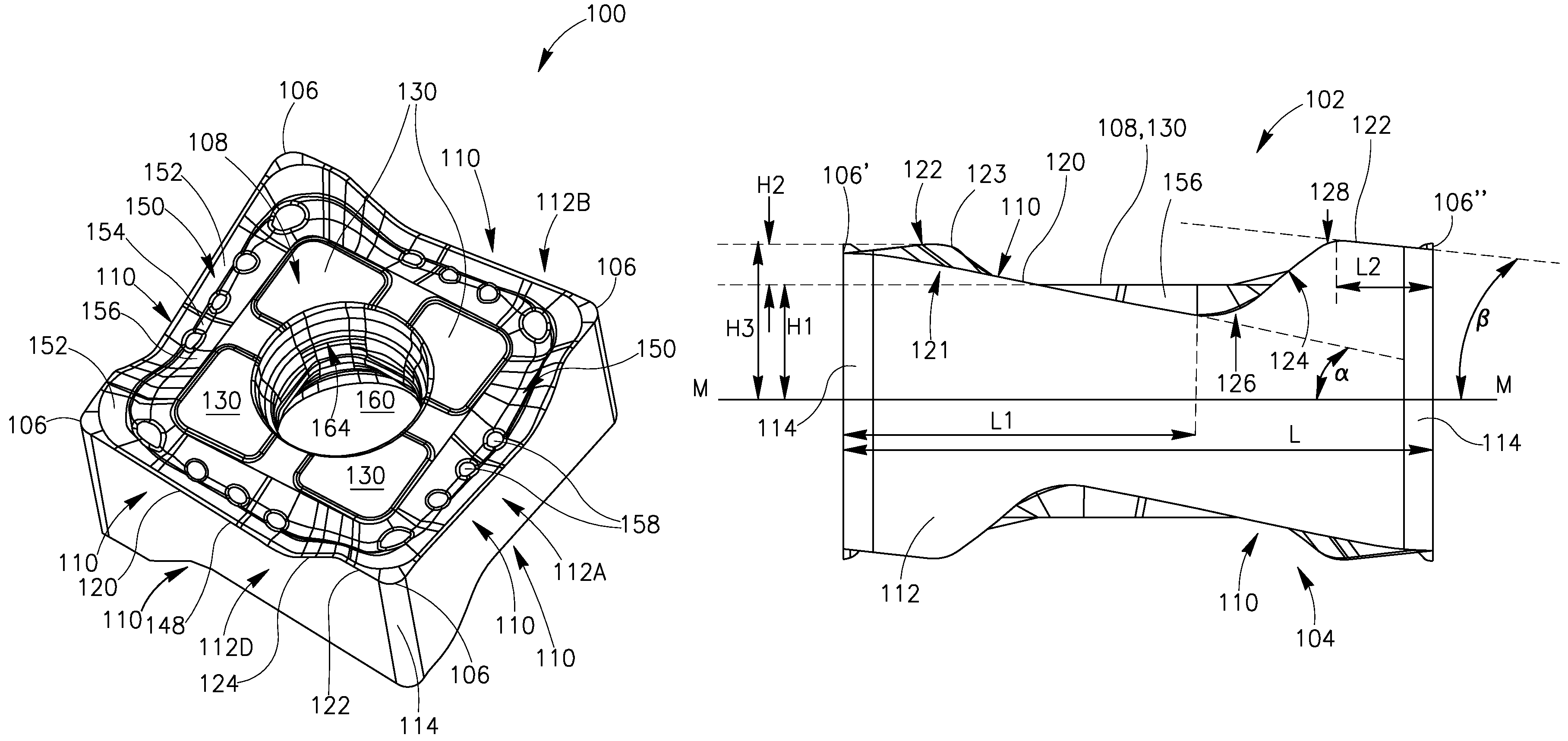
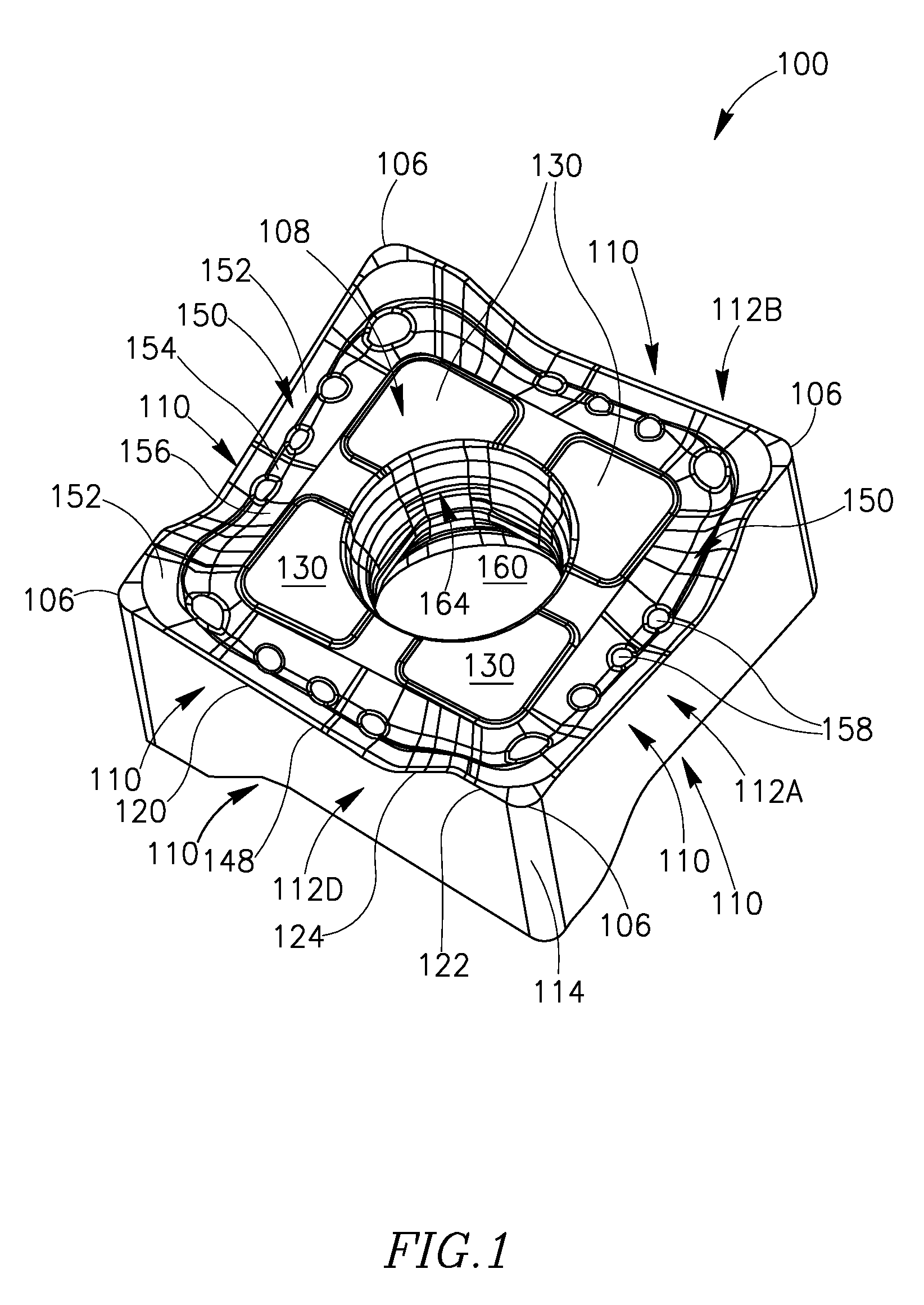
[0037]FIGS. 1-5 show one embodiment of a cutting insert 100 in accordance with the present invention. Cutting insert 100 is preferably formed from carbide or other material by pressing and sintering, injection molding, or other known manner.

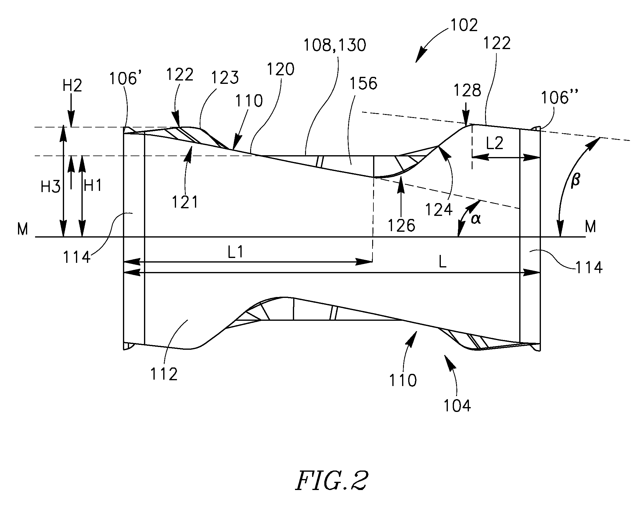
[0038]Cutting insert 100 is double-ended (i.e., reversible) with each end being four-way indexable, providing a total of eight cutting positions. The insert's first end surface 102 and second end surface 104 face in opposite directions and are substantially square in an end view (see FIG. 3). Each end surface is provided with an associated abutment surface 108 in a central region thereof, and four associated insert corners 106. As seen in FIGS. 2 and 4, the insert corners 106 do not form the high points, in a side view of the cutting insert.

[0039]The cutting insert 100 has four side surfaces 112A, ...


PUM

PropertyMeasurementUnit
βaaaaaaaaaa
βaaaaaaaaaa
βaaaaaaaaaa

Abstract

A fully indexable square cutting insert has four side surfaces connecting to two end surfaces. At the intersection of each side surface with an end surface is a primary cutting edge which extends from an insert corner and along a first side surface, in a downward direction towards a median plane. A wiper extends from the same insert corner and along an adjacent side surface, in an upward direction away from the median plane, to rise above an abutment surface of an associated end surface. The geometry of the cutting insert and of the insert pocket in which the insert is seated are such that the primary cutting edge has a positive axial angle (helix), while the insert has an overall negative axial angle for providing axial clearance and an overall negative radial angle for providing radial clearance.

Description

FIELD OF THE INVENTION[0001]The current invention relates to a cutting insert of the sort used in milling cutters. More particularly, it concerns a cutting insert having a square footprint and capable of forming a 90° cut in a work piece.BACKGROUND OF THE INVENTION[0002]There are numerous metal cutting applications requiring that a 90° shoulder be cut in a work piece. To make a 90° shoulder, a cutting insert seated in a tool preferably employs an operative primary cutting edge in conjunction with a wiper (sometimes referred to as a ‘secondary’ cutting edge) to which it is connected via a corner. Such a cutting insert needs the following clearances with respect to the tool: a primary cutting edge relief angle, a wiper relief angle, and relief between any non-operative cutting edges at the work piece.[0003]U.S. Pat. No. 6,336,776 discloses a fully indexable negative geometry polygonal insert for machining a square (or 90°) corner, in a work piece. The disclosed insert uses an operativ...

Claims


Application Information

Patent Timeline
Patent Type & Authority Patents(United States)
IPC IPC(8): B23B27/16B23C5/20
CPCB23C5/06B23C5/2221B23C2200/205B23C2200/286Y10T407/235B23C2210/168Y10T407/1924Y10T407/245Y10T407/23B23C2210/045B23C5/2213
Inventor BHAGATH, KEDAR SURESH
Owner TAEGUTEC INDIA P
Why Eureka
Try Eureka