Roof ridge vent having honeycomb or like ventilation material

a technology of ventilation material and honeycomb, which is applied in ventilation systems, lighting and heating apparatus, heating types, etc., can solve the problems of unreasonable cooling energy requirements and uncomfortable living quarters of buildings, and achieve the effect of preventing weather infiltration

Active Publication Date: 2009-10-20
BENJAMIN OBDIKE
View PDF15 Cites 31 Cited by
  • Summary
  • Abstract
  • Description
  • Claims
  • Application Information

AI Technical Summary

Problems solved by technology

Such ventilation prevents undue heat buildup, which can render the living quarters of the building uncomfortable and impose unreasonable energy requirements for cooling.

Method used


Image

  • Roof ridge vent having honeycomb or like ventilation material
  • Roof ridge vent having honeycomb or like ventilation material
  • Roof ridge vent having honeycomb or like ventilation material

Examples


first embodiment

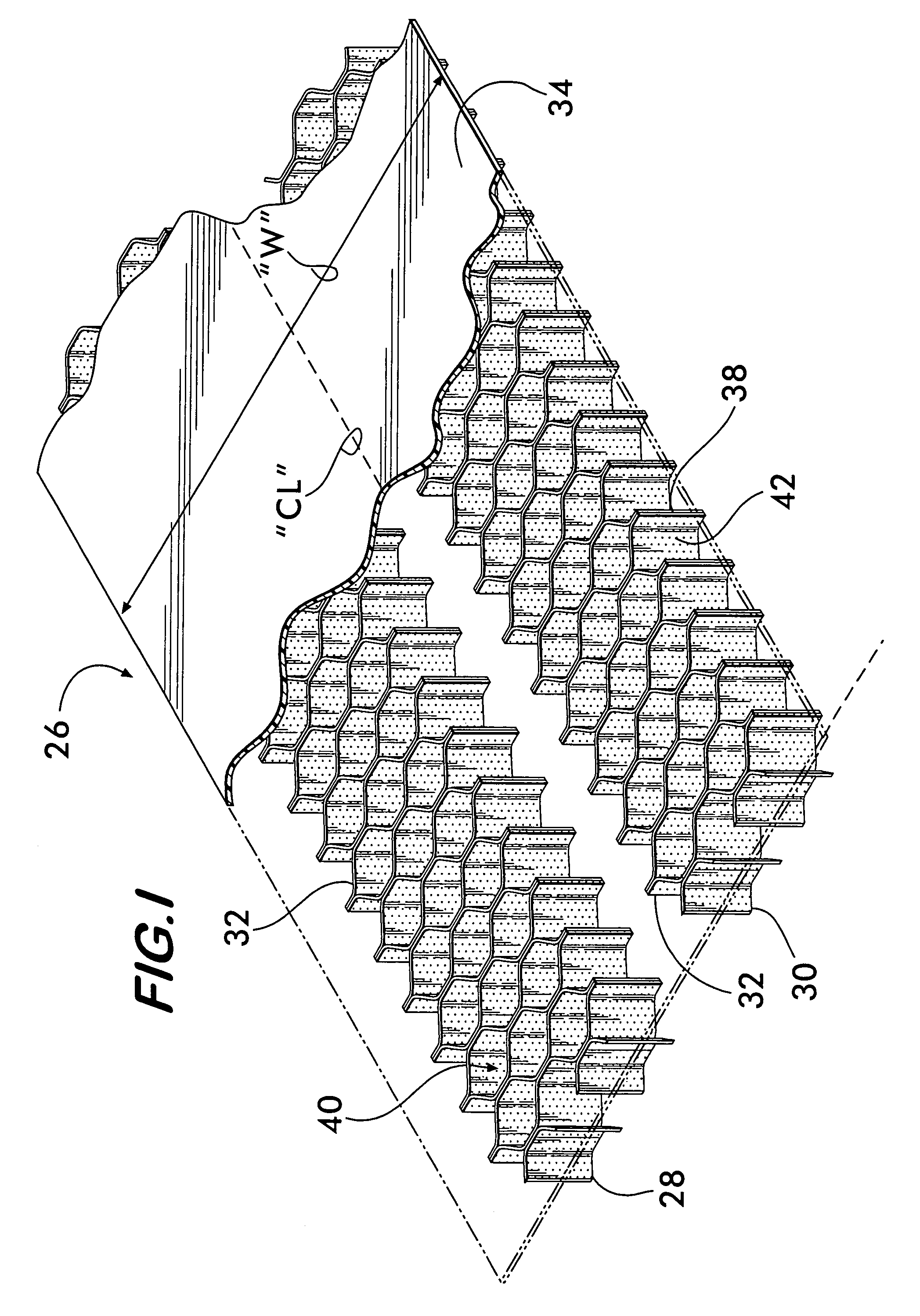
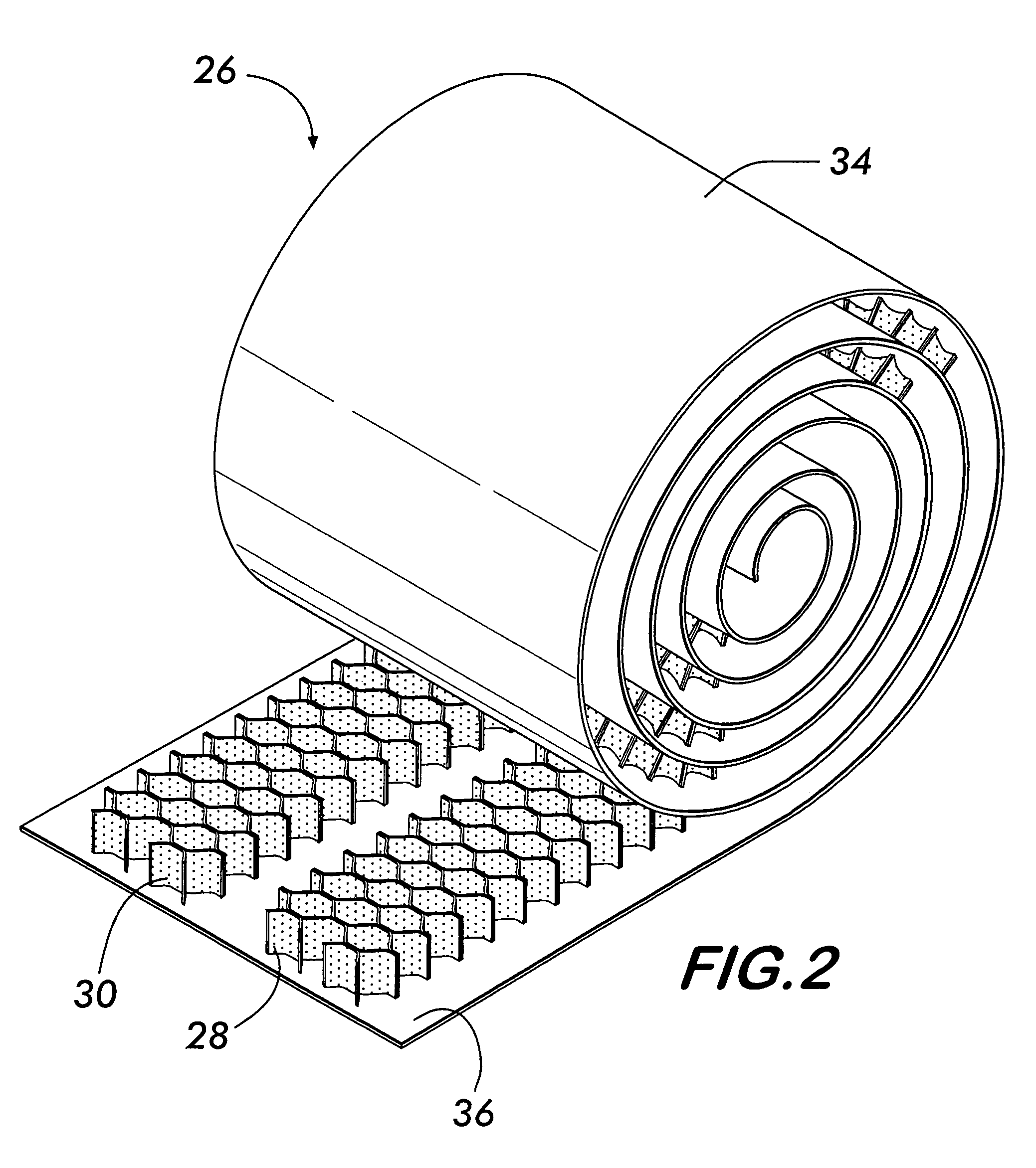
[0028]Turning to the present invention illustrated in FIGS. 1-4, a vent 26 has a pair of continuous, elongate strips of honeycomb material, 28 and 30, each with an upper face 32 bonded to the underside 36 of a continuous, elongate backer sheet material 34. As best illustrated in FIG. 2, the honeycomb material and backer sheet combination can be rolled into a spiral during or after manufacture, stored and transported in roll-form, and unrolled during installation on a roof ridge. The strips of the honeycomb material, 28 and 30, can be, for instance, adhesively or thermally bonded to the backer material 34 on opposite sides of a longitudinally-extending centerline “CL” of the backer material 34 so that, when installed, the strips, 28 and 30, extend on opposite sides of the open slot 22 in the roof ridge 16. See FIG. 3. The backer sheet 34 can be made of a plastic, thermoplastic, fabric, non-woven fabric, cardboard, metal or like material.

[0029]When installed on a roof ridge 16 as illu...

second embodiment

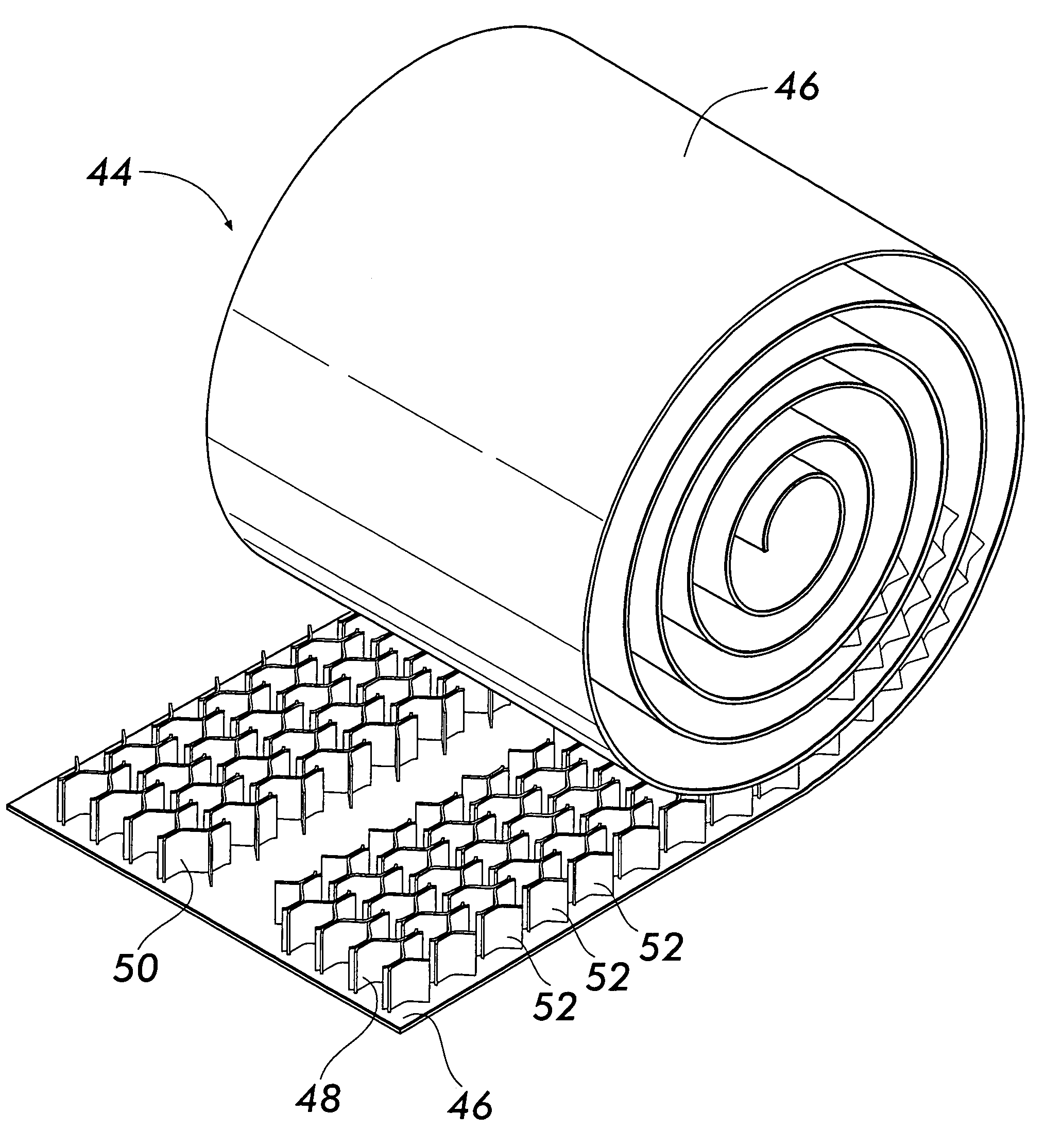
[0030]A second embodiment according to the present invention is illustrated in FIGS. 5-9. Similar to the first embodiment, vent 44 includes a backer sheet 46 to which a pair of honeycomb ventilation material strips, 48 and 50, are bonded. However, in this embodiment the walls 52 of the honeycomb material are preferably impermeable to air and moisture and are provided as discontinuous cut sections 52. Thus, each strip, 48 and 50, includes a plurality of cut honeycomb sections 52 that are spaced-apart and offset from adjacent sections 52 thereby forming an undulating open ventilation path 54 between each adjacent pair of sections 52. See FIG. 8. A benefit of using an undulating ventilation path instead of a straight ventilation path is that weather infiltration to the slot 22 due to blowing rain and / or snow is reduced.

[0031]Additional weather infiltration protection can be provided to vent 44 by providing the outermost edge wall 56 of each honeycomb section 52 with the ability to flex...

third embodiment

[0032]A third embodiment according to the present invention is illustrated in FIGS. 10-13. A vent 60 is constructed entirely, or substantially entirely, of a continuous elongate strip of honeycomb ventilation material 62, without a backer sheet or the like. The upper surface 64 of the honeycomb material 62 directly supports cap shingles 20 or the like thereon, and the underside 66 confronts the underlying roof surface. The honeycomb material 62 is sufficiently strong to support cap shingles 20 that are nailed to the roof 10 above the surface of the roof ridge 16, and the walls 68 and cavities 70 of the honeycomb material 62 are air permeable permitting air to vent laterally therethrough to the side edges, 72 and 74, of the vent 60. See FIG. 13. The longitudinally-extending central section 76 of the vent 60 includes an inverted-V cut 78 or the like to permit the honeycomb material 62 to flex about the roof ridge 16 and conform to the shape of the roof ridge 16.

[0033]By way of example...


PUM


Abstract

A roof ridge vent and installation includes a ventilation material having walls defining a plurality of separate open cellular cavities, such as a honeycomb material, that may or may not extend from the underside of a separate sheet material. Preferably, the walls of the ventilation material extend substantially vertically within the vent, and paths of ventilation, which extend from on open slot on the roof ridge to either longitudinally-extending side edge of the vent, extend transversely through the walls of the ventilation material. To this end, the walls are perforated or are made of an air permeable material, more preferably, a non-wicking hydrophobic material or a non-woven fabric having a multiplicity of closely spaced openings. Alternatively, paths of ventilation can be provided by channels formed between adjacent, spaced-apart sections of the ventilation material. Preferably, the vent is continuous and elongate and is stored and shipped in a spiral roll.

Description

CROSS-REFERENCE TO RELATED APPLICATIONS[0001]This application claims the benefit under 35 USC §119(e) of U.S. Provisional Patent Application No. 60 / 617,151, filed Oct. 8, 2004.BACKGROUND OF THE INVENTION[0002]The present invention relates to a roof ridge vent that enables the circulation of air between a roof of a building and an underlying ceiling structure.[0003]It is useful, and in many locales a building code requirement, that the attic area of a building be provided with a means to permit air exchange. Such ventilation prevents undue heat buildup, which can render the living quarters of the building uncomfortable and impose unreasonable energy requirements for cooling. Proper ventilation of the attic area also tends to preserve the structural integrity of the roof and roof coverings. One method of venting the roof structure consists of applying a venting media over a slot present along the ridge of a roof. These types of vents are known as ridge vents.[0004]Examples of ridge ve...

Claims


Application Information

Patent Timeline
Patent Type & Authority Patents(United States)
IPC IPC(8): F24F7/02
CPCF24F7/02E04D13/176
Inventor COULTON, MICHAEL SCARUSO, GEORGE
Owner BENJAMIN OBDIKE
Why Eureka
Try Eureka