Applicator attachable to skin treatment device and skin treatment method using the same

a skin treatment device and application technology, applied in the field of applications attachable to skin treatment devices and skin treatment methods, can solve the problems of patient skin burning, etc., and achieve the effect of removing any unpleasant feelings or pain

Active Publication Date: 2009-10-20
JUN CORP
View PDF41 Cites 7 Cited by
  • Summary
  • Abstract
  • Description
  • Claims
  • Application Information

AI Technical Summary

Benefits of technology

[0011]In order to overcome the aforementioned conventional problems, the first purpose of the present invention is to provide a skin treatment device adopting an applicator and a skin treatment method using the applicator. The applicator attachable to the skin treatment device is provided with a vacuum cavity for sucking up the patient's skin between the pair of electrodes in order to eliminate any unpleasant feelings or pain during the skin treatment.
[0012]The second purpose of the present invention is to focus the effective treatment in the dermis while maximizing the cooling efficiency for not only maintaining a moderate skin temperature, but also preventing possible skin burns. When the high frequency wave flows between the pair of electrodes, heat is generated at each electrode. If excessive heat is generated, it may cause the patient's skin to burn. Thus, it is necessary to precisely control the electrode temperature to prevent possible damage to the patient.
[0013]The third purpose of the present invention is to form a hot spot in the dermis by illuminating a specific frequency of optical energy onto the patient's skin for maximizing the skin treatment effect. The laser beam of 915 nm is suitable to use for the optical energy. A heating spot is formed by concentrating the heat energy from the high frequency wave flowing between the pair of electrodes (3) and diode laser beams penetrating the dermis. Therefore, the heating spot will effectively produce collagen in the dermis.
[0014]The fourth purpose of the present invention is to provide a relief process after the skin treatment by emitting a specific frequency wave. The treated skin builds up stress and tension because of the stimulation during the skin treatment. Therefore, the relief process cures the skin organs to be stable and prevents possible skin damage by relieving the stress and tension. A red light is suitable for the specific frequency wave.
[0018]Further, a filter (22) is provided on the flow passage (21) for preventing foreign objects on the patient's skin from being sucked in.
[0027]Further, a cooling process may be added between the above (a) step and (d) step for (b) cooling the patient's skin to protect it from possible overheating.

Problems solved by technology

If excessive heat is generated, it may cause the patient's skin to burn.

Method used


Image

  • Applicator attachable to skin treatment device and skin treatment method using the same
  • Applicator attachable to skin treatment device and skin treatment method using the same
  • Applicator attachable to skin treatment device and skin treatment method using the same

Examples


implementing example 1

[0052]Hereinafter, the applicator attachable to the skin treatment device according to the first embodiment of the present invention is described in detail with reference to the accompanying drawings.

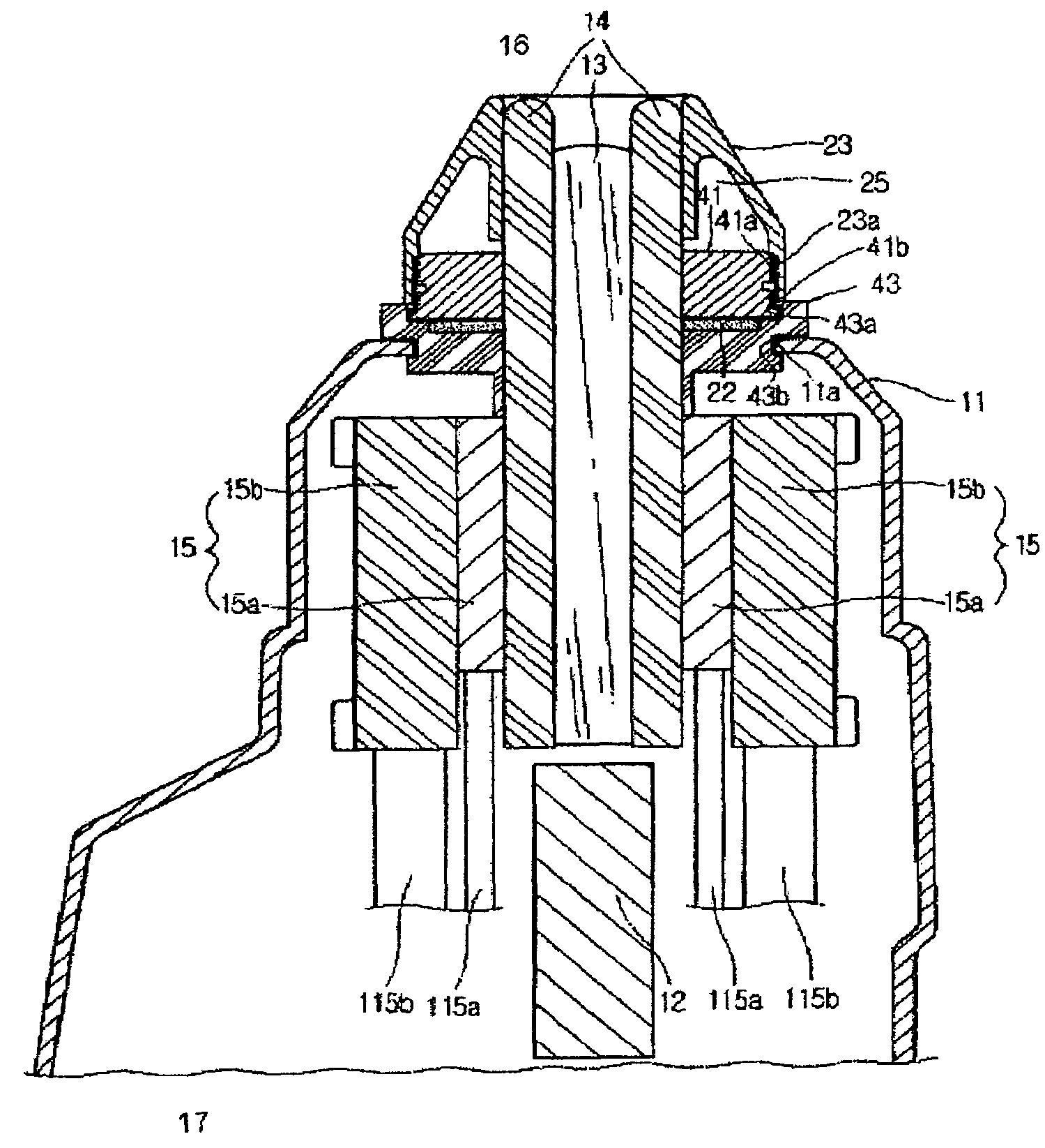
[0053]Accordingly, FIG. 4 is a front cross-section of the applicator attachable to the skin treatment device according to the first embodiment of the present invention. FIG. 5 is a side cross-section of the applicator attachable to the skin treatment device according to the first embodiment of the present invention.

[0054]As shown in FIGS. 4 and 5, the applicator attachable to the skin treatment device of the first embodiment of the present invention comprises mainly a housing (11), a diode laser emitter (12), a permeating element (13), a pair of electrodes (14) and a cooling unit (15).

[0055]Though the overall features of the housing (11) are shaped like a handgun, only the front portions of the housing and capsule are shown in the presented drawings.

[0056]The diode laser emitter (12), w...

implementing example 2

[0083]Hereinafter, the applicator attachable to the skin treatment device according to the second embodiment of the present invention is described in detail with reference to the accompanying drawings.

[0084]Accordingly, FIG. 6 shows a side cross-section of an applicator attachable to the skin treatment device according to the second embodiment of the present invention.

[0085]As shown in FIG. 6, the applicator attachable to the skin treatment device of the second embodiment comprises: a housing (100) for protecting the inner mechanisms, a unipolar electrode (110) that is arranged inside of the housing for generating high frequency radiation, and a capsule (130) forming a suction cavity (121) at an inlet portion, which one end of the electrode (110) contacts a patient's skin and the opposite end of the electrode (110) is attached to the housing, an inner space (122) connected to the suction cavity (121), and a flow passage (125) for interconnecting between a vacuum unit and the inner s...


PUM


Abstract

An applicator attachable to a skin treatment device that is capable of simultaneously applying RF energy and optic energy to a patient's skin, and a skin treatment method using the applicator are developed. The skin treatment device comprises: a housing, one or pair of electrodes arranged inside of the housing for generating the high frequency waves, a suction cavity formed in front of the electrodes while it is contacting to the patient's skin, opposite end installed to the housing and an lateral vacuum pocket that is connected to a flow pathway connected to a vacuum system for generating negative pressure inside the applicator. Thus, the patient's skin is lifted by suction force to place between the pair of electrodes for easily and effectively penetrating the laser beams in to the dermis.

Description

BACKGROUND OF THE INVENTION[0001]1. Field of the Invention[0002]The present invention relates to an applicator attachable to a skin treatment device and a skin treatment method using the applicator. More particularly, the applicator attachable to the skin treatment device, being capable of simultaneously applying RF energy and diode laser energy, provides a means to lift the skin via suction and place it between the electrodes to allow the high frequency rays to effectively penetrate and form collagens in the deep dermis.[0003]2. Description of the Related Art[0004]Commonly, a skin treatment device is used for removing tiny wrinkles, acne scars, acnes, pore contractions, darkened age spots and hairs for improving skin conditions such as skin color or skin organs.[0005]As shown in FIG. 1, a conventional skin treatment device is equipped with a separate applicator, which is connected to the main body for simultaneously applying the RF energy and diode laser energy.[0006]As shown in FI...

Claims


Application Information

Patent Timeline
Patent Type & Authority Patents(United States)
IPC IPC(8): A61B18/18A61N5/06
CPCA61B18/203A61H7/008A61N1/40A61N5/0616A61N1/328A61B2018/0047A61H2201/0228A61H2201/0292A61H2201/10A61N2005/0662A61N2005/0649A61N2005/0651A61N2005/0659A61N1/06A61N5/06
Inventor JUN, YONG GYU
Owner JUN CORP
Why Eureka
Try Eureka