Integrated security switch

a security switch and integrated technology, applied in the field of network connectivity and security, can solve the problems of system failure to meet the needs of network security, system failure to meet security requirements, and inability to monitor the security of the network,

Active Publication Date: 2009-10-20
FORTINET
View PDF12 Cites 63 Cited by
  • Summary
  • Abstract
  • Description
  • Claims
  • Application Information

AI Technical Summary

Benefits of technology

[0006]It is an object of the present invention to obviate or mitigate at least one disadvantage of previous UTM devices by introduction of an integrated security switch incorporating layer 2 and / or layer 3 switching characteristics and unified threat management characteristics with a single management interface.

Problems solved by technology

Such systems, however, suffer from continuous software-patch management, access control and review, penetration testing, and vulnerability assessments.
This is a labor intensive and expensive manner of ensuring adequate and timely connectivity and security.
Threats to a network are readily apparent outside of almost any firewall.
These include a continual stream of low-level network attacks, peppered from time to time with serious break-in attempts by computer hackers and malicious code including virus-infected E-mails, worms, spam, and spyware.
While this is a potential way to solve the problem of implementing a secured network infrastructure, it increases network complexity and administrative overhead.
There are also situations when critical traffic required by the security device to determine if network attacks are occurring is “absorbed” by the switch minimizing the effectiveness of the security device.
While such systems can offer cost-effective coordination between organizations and between technologies by streamlining administration and interoperability, certain bundling of key information-security functions and simplified administration remain obstacles to effective unified threat management.

Method used


Image

  • Integrated security switch
  • Integrated security switch
  • Integrated security switch

Examples


first embodiment

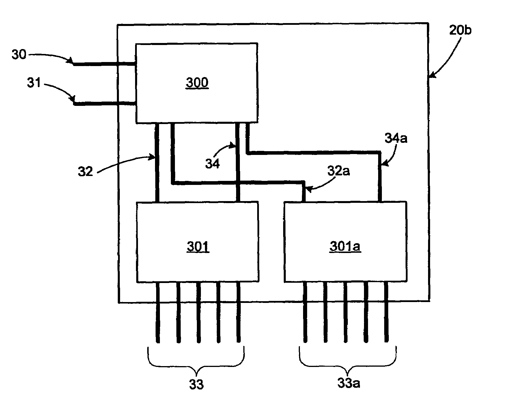
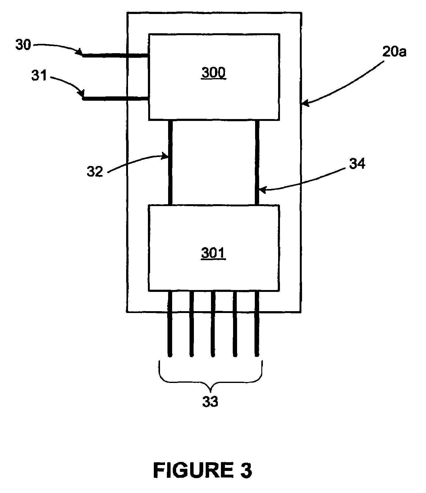
[0018]The integrated security switch 20 as shown in FIG. 2 includes two main hardware modules—a security module and switch module. Such are further shown in a first embodiment within FIG. 3. Within the integrated security switch 20a shown in FIG. 3, security module 300 is connected to switch module 301 via a management path 32 for management of communications and a traffic path 34 for transmission of the actual communications. While only one of each such path 32, 34 are shown, it should be understood that more than one of each such paths may exist without straying from the intended scope of the present invention depending upon the given network requirements (e.g. user capacity).

[0019]With further reference to FIG. 3, external communications connections 30 and 31 are shown for linkage of the integrated security switch 20a to the Internet or other networks. Further, switch ports 33 (e.g., Ethernet ports) are shown for linkage of the integrated security switch 20a to user devices (e.g....

second embodiment

[0023]It should be understood that the present invention is scalable for a variety of networking applications. For instance, multiple LANs can be supported by an integrated security switch of the present invention that includes segmented switching functions. While FIG. 3 shows a logical representation of the present invention with one security module and one switch module as discussed above, it is feasible that multiple switch modules could be supported by one security module. Such a logical representation of the present invention with one security module and two switch modules is shown in FIG. 4. In either the embodiment, module integration is accomplished using available chipset communications links. Although separate modules are shown within either FIG. 3 or 4, this should be considered as merely illustrative of the logical representation such that a single hardware layout is one possible implementation. Still further, multiple switching modules should be understood to be illustr...


PUM


Abstract

An integrated security switch and related method for managing connectivity and security among networks. The integrated security switch includes a security function connectable with a first network and at least one switching function connectable with a second network. A common management interface driven by both command line interface and graphic user interface protocols manages the switching function via a management path dedicated between the security function and the switching function. The common management interface enables secure switching of traffic to flow via a traffic path dedicated between the switching function and the security function. Typically, the traffic is a flow of data between the Internet and a group of networked users such as a wide area network.

Description

FIELD OF THE INVENTION[0001]The present invention relates generally to network connectivity and security. More particularly, the present invention relates to an integrated security switch for improved network connectivity and security.BACKGROUND OF THE INVENTION[0002]Within the field of networking and internetworking, communications and information traffic continues to grow. Increases to computer processing speeds and enhanced transmission mediums such as optical fiber and Internet-capable cellular phones further add to the amount of potential network traffic. In parallel, increased network traffic corresponds to still further increases in the variety of information moving through the network. Businesses are interconnecting more with each other, with customers, with vendors, with government agencies, and with the public. Two major concerns within such an increasingly busy network are managing the movement of such traffic and ensuring the integrity of information content in terms of ...

Claims


Application Information

Patent Timeline
Patent Type & Authority Patents(United States)
IPC IPC(8): H04L12/28G06F15/16H04L12/66H04L47/20
CPCH04L63/02H04L63/0209H04L47/20H04L63/0281
Inventor XIE, MICHAELSHANG, JINJAMES, ANTHONYWEI, SHAOHONG
Owner FORTINET
Why Eureka
Try Eureka