Scalable transceiver based repeater

a transceiver and repeater technology, applied in electromagnetic repeaters, wavelength-division multiplex systems, electrical apparatus, etc., can solve the problems of limited transmission distance of optical signals, degraded optical signals carried by optical networks, and limited distance that optical signals can be transmitted, so as to achieve less expensive manufacturing

Active Publication Date: 2009-10-20
II VI DELAWARE INC
View PDF3 Cites 9 Cited by
  • Summary
  • Abstract
  • Description
  • Claims
  • Application Information

AI Technical Summary

Benefits of technology

[0011]These and other limitations are overcome by the present invention, which relates to systems and methods for transmitting optical signals and more particularly to a scalable transceiver based repeater for repeating optical signals in an optical network. One advantage of a scalable transceiver based optical repeater is that the components can be standards based and are thus less expensive to manufacture.
[0012]One embodiment of a scalable transceiver based repeater includes a base with one or more receptacles configured to receive transceivers. An optical signal (such as a Wavelength Division Multiplexed optical signal) that includes multiple channels is demultiplexed and each of the transceivers mounted in the receptacles receives a different channel. If a particular channel of the optical signal is not being used, there is no need to have a transceiver for that channel. This makes the repeater scalable and expandable as needed because transceivers can be added for other channels or wavelengths in the optical signal as the other channels or wavelengths of light are used. In addition, transceivers that fail can be replaced individually without having to replace other transceivers in the scalable repeater. Each transceiver therefore repeats a particular channel of the optical signal. More particularly, the lasers in the transceivers generate the wavelengths that correspond to the channels in the optical signal.
[0014]As a channel received at a receiver portion of a transceiver is retransmitted by the transmit portion of the transceiver, the channel is converted to an electrical signal by the receiver, processed, and then converted back into an optical signal by the transmit portion. Advantageously, the transmitter regenerates the channel and effectively resets the jitter budget of the channel. Also, problems with noise accumulation and amplification in optical amplifiers is avoided as each channel is retransmitted by the transceivers at the various wavelengths. The transmitter portions of the transceivers may also be associated with a CDR circuit. The CDR circuit can help remove noise and reset the jitter budget of the channel. The scalable transceiver based repeater is scalable and pluggable.

Problems solved by technology

An underlying problem of optical networks is that optical signals carried by the optical networks are degraded during transmission for a wide variety of reasons.
Because optical signals degrade during transmission, the distance that an optical signal can be transmitted is limited.
Without optical amplifiers, the ability to transmit optical signals could be limited.
In spite of these advantages, optical amplifiers have several drawbacks that need improvement.
For example, optical amplifiers are often analog in nature and they therefore introduce noise into the optical signals.
As noise is added to an optical signal, the likelihood of introducing errors or of being unable to read the optical signal increases.
The problem of added noise becomes more pronounced when optical amplifiers are cascaded, because the noise accumulates at each optical amplifier.
As a result, each subsequent optical amplifier, in addition to introducing new noise to the optical signal, amplifies the noise that was added by prior optical amplifiers.
The addition of noise and the amplification of the added noise ultimately results in a corrupted optical signal.
Unfortunately, optical amplifiers do not always provide the same amount of gain to each channel included in the optical signal.
Another problem associated with optical amplifiers is that they often lack scalability.
When an optical amplifier fails, all of the channels of the optical signal are adversely affected.
The optical amplifier cannot be fixed, but likely needs to be replaced.
In other words, optical amplifiers are not pluggable.
Optical amplifiers are also unable to reset the jitter budget of an optical signal.
In fact, this is one of the reasons that optical amplifiers, when cascaded to repeat optical signals, ultimately fail.
The jitter budget is exhausted and the optical signal can no longer be recognized.

Method used


Image

  • Scalable transceiver based repeater
  • Scalable transceiver based repeater
  • Scalable transceiver based repeater

Examples


Embodiment Construction

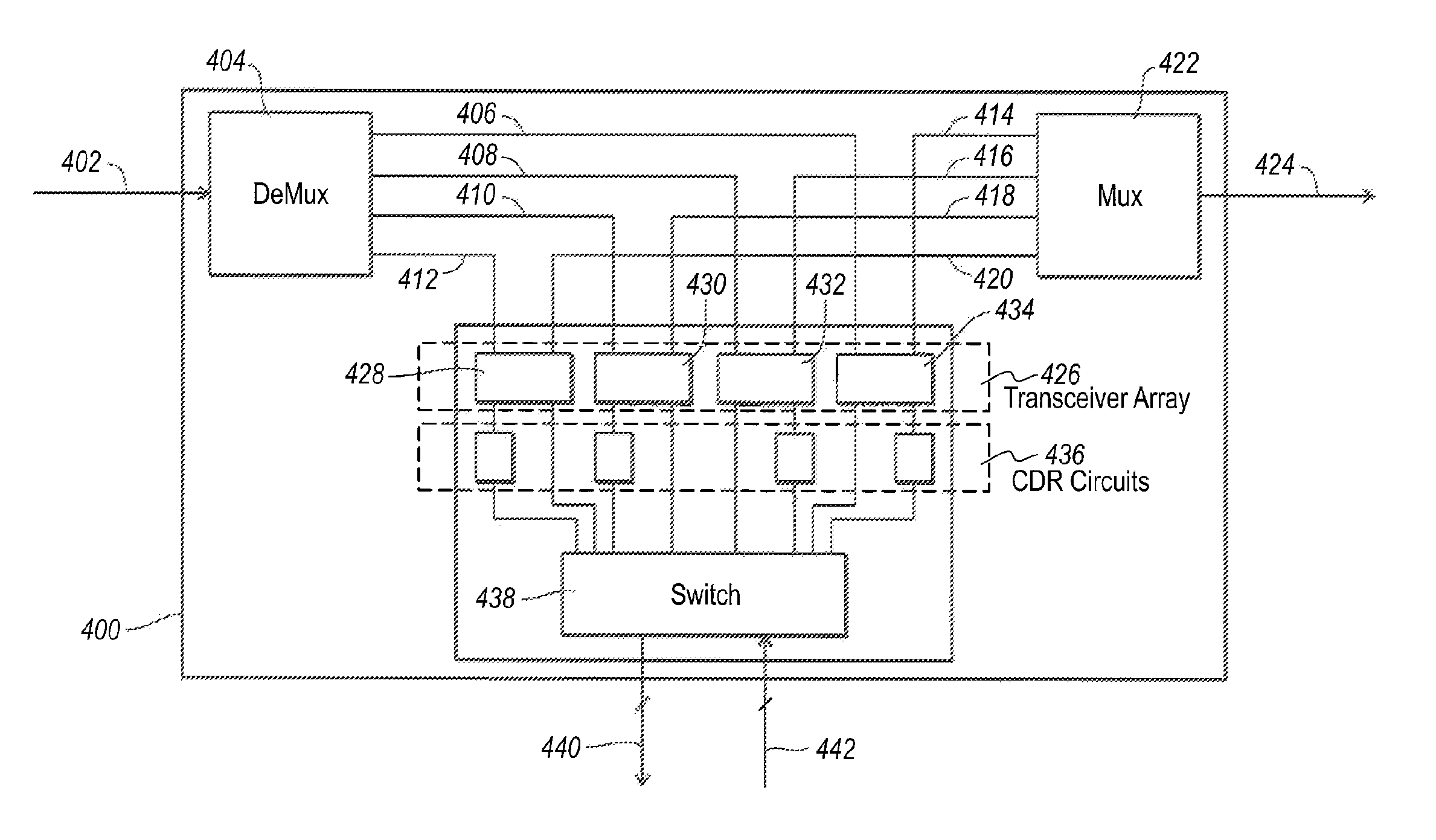
[0022]The present invention relates to systems and methods for transmitting optical signals and more particularly to a scalable transceiver based repeater for repeating or retransmitting optical signals. In one embodiment, the repeater includes a transceiver for at least some of the channels or wavelengths in an optical signal. Each transceiver detects a particular channel (or wavelength) of an optical signal with an optical receive portion that is typically referred to as a receiver optical sub-assembly (ROSA). Each transceiver also has a corresponding transmit portion often referred to as a transmitter optical sub-assembly (TOSA) to transmit the wavelength of the channel received by the receive portion of the transceiver.

[0023]One of skill in the art can appreciate that as the channels, also referred to herein as signals, are processed by the ROSA or the TOSA, the channels or signals may take either an electrical or optical form. A ROSA, for example, receives and optical channel o...


PUM


Abstract

Systems and methods for repeating optical signals. A scalable transceiver based repeater includes one or more transceivers. Each transceiver includes an optical receiver that receives a channel of an optical signal. The optical transmitter in each transceiver transmits the channel received by the associated optical receiver. A switch is used to redirect the channels, which may be in an electrical form at the switch, from the optical receivers back to the optical transmitters. The switch can also be used to add / drop the channels from the repeater. The optical transmitter and / or the optical receiver of each transceiver may also include a clock / data recovery circuit (CDR). The repeater is scalable because transceivers can be added / replaced as needed. A demultiplexor can separate an optical signal into the channels that are received by the optical receivers. A multiplexor combines the channels generated by the optical transmitters.

Description

CROSS-REFERENCE TO RELATED APPLICATIONS[0001]This application claims the benefit of U.S. Provisional Application No. 60 / 566,664, filed Apr. 30, 2004, and entitled SCALABLE TRANSCEIVER BASED REPEATER, which is hereby incorporated by reference.BACKGROUND OF THE INVENTION[0002]1. The Field of the Invention[0003]The present invention relates to the transmission of optical signals in a network. More particularly, the present invention relates to optical repeaters and more specifically to scalable transceiver based optical repeaters.[0004]2. Background and Relevant Art[0005]An underlying problem of optical networks is that optical signals carried by the optical networks are degraded during transmission for a wide variety of reasons. Signal noise, signal loss, signal attenuation, chromatic dispersion, and modal dispersion are examples of the deleterious effects experienced by optical signals in optical networks. Because optical signals degrade during transmission, the distance that an opti...

Claims


Application Information

Patent Timeline
Patent Type & Authority Patents(United States)
IPC IPC(8): H04B10/02H04B10/00H04B10/29H04J14/02
CPCH04J14/0201H04B10/29
Inventor HOFMEISTER, RULDOLF J.
Owner II VI DELAWARE INC
Why Eureka
Try Eureka