
Contoured seat and method

a seat and coccyx technology, applied in the field of orthopedic supports, can solve the problems of significant economic costs, back injuries, lost productivity of workers, etc., and achieve the effects of reducing muscle tension, reducing muscle tension and strain, and reducing sacrum and coccyx pressur

Inactive Publication Date: 2009-10-27
GREGORY MATTHEW WAYNE +1
View PDF15 Cites 32 Cited by
  • Summary
  • Abstract
  • Description
  • Claims
  • Application Information

AI Technical Summary

Benefits of technology

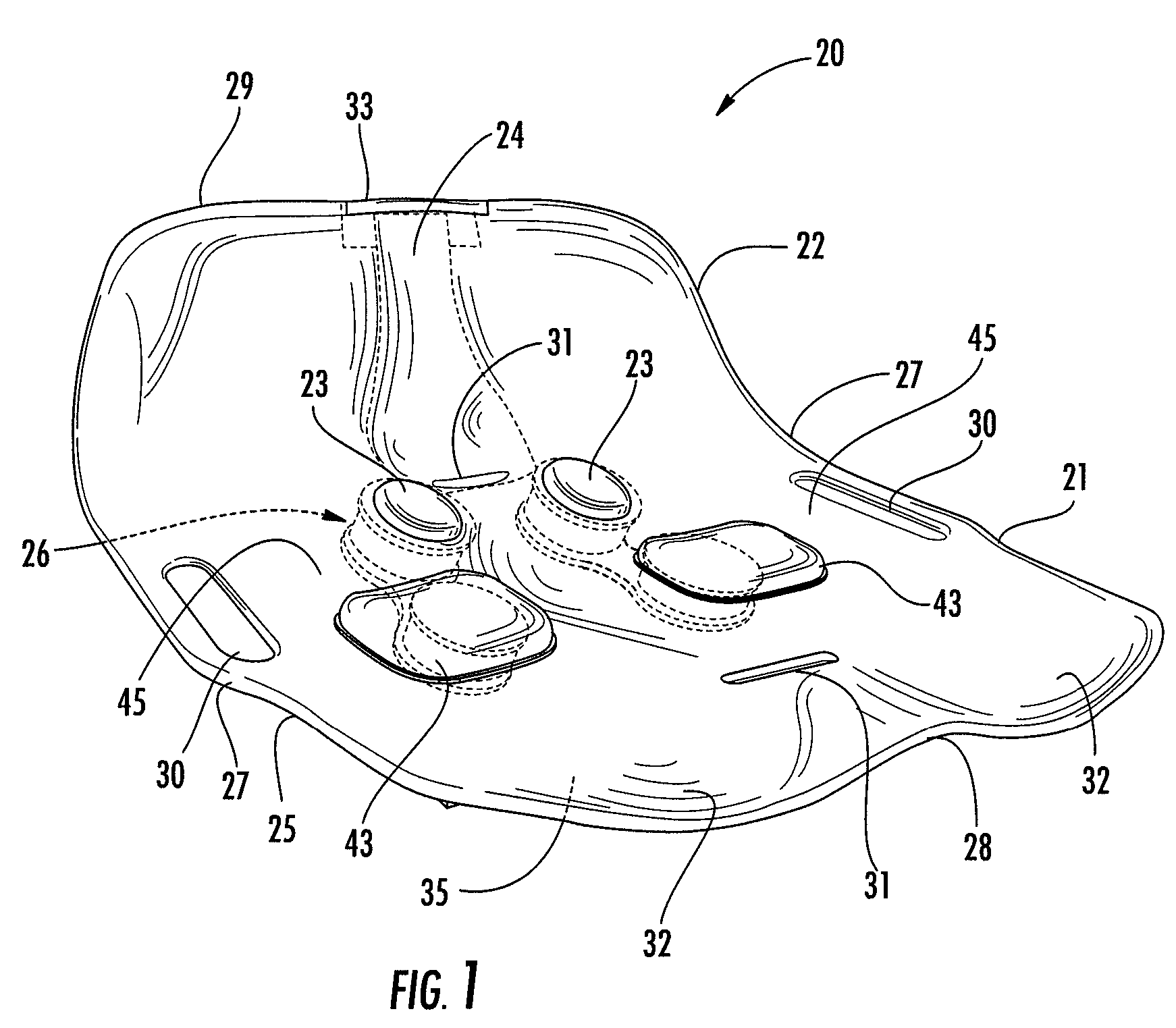
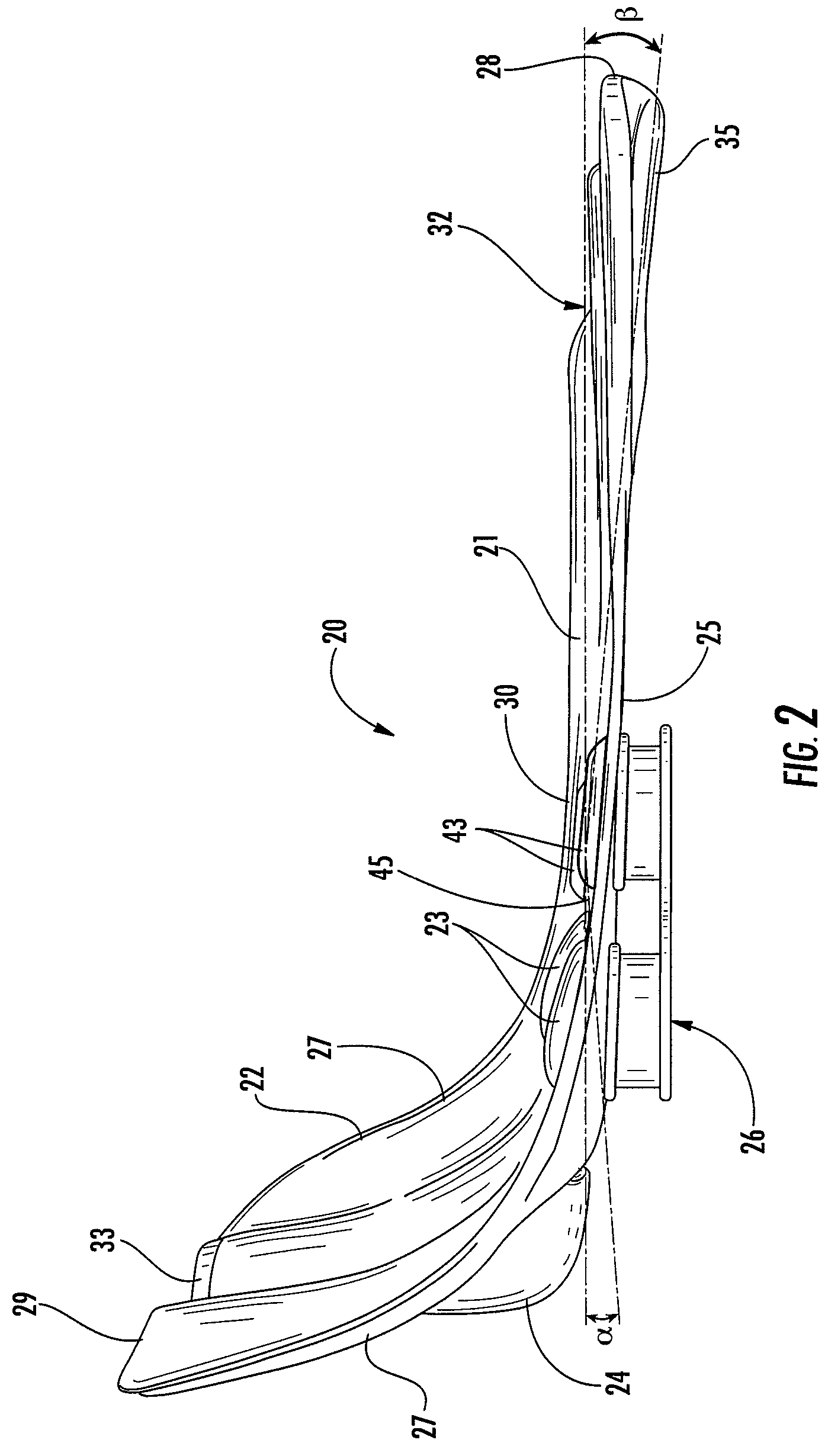
[0011]The contoured seat and method of the present invention has many advantages. Providing specifically angled support surfaces (due to the angle of inclination of the surfaces) aligns the pelvis and lumbar spine as well as reduces pressure on the sacrum and coccyx. Generally, these support surfaces ensure that the pelvis is positioned at about a 15° angle and that the lumbar lordosis is maintained at about a 60° angle. The piriformis supporting ovals apply pressure to the difficult to stretch piriformis musculature. Overall, these positions reduce muscle tension and strain and reverse the incorrect rearward pelvic tilt of conventional ergonomic seating systems. For example, the shapes defined by the seating surface and back surface reduce muscle tension in the lower back when tested with surface dwelling electromyography (EMG) electrodes. In addition, x-ray testing reveals an increase in lordosis in the lumbar spine. These changes result in less fatigue and pain for the user.

Problems solved by technology

Lower back injuries (chronic and acute) are a massive problem in the United States, leading to significant economic costs due to the expense of treatment and the lost productivity of workers.
These injuries are especially prevalent in workers that have intermittent labor duties between which they spend long times in a seated position.
This not only causes back injuries, but also exacerbates existing chronic and acute injuries.
However, time is not always available for such appointments and the adjustments need to be maintained in between appointments.

Method used


Image

  • Contoured seat and method
  • Contoured seat and method
  • Contoured seat and method

Examples


Embodiment Construction

[0022]The present invention now will be described more fully hereinafter with reference to the accompanying drawings, in which some, but not all embodiments of the inventions are shown. Indeed, these inventions may be embodied in many different forms and should not be construed as limited to the embodiments set forth herein; rather, these embodiments are provided so that this disclosure will satisfy applicable legal requirements. Like numbers refer to like elements throughout.

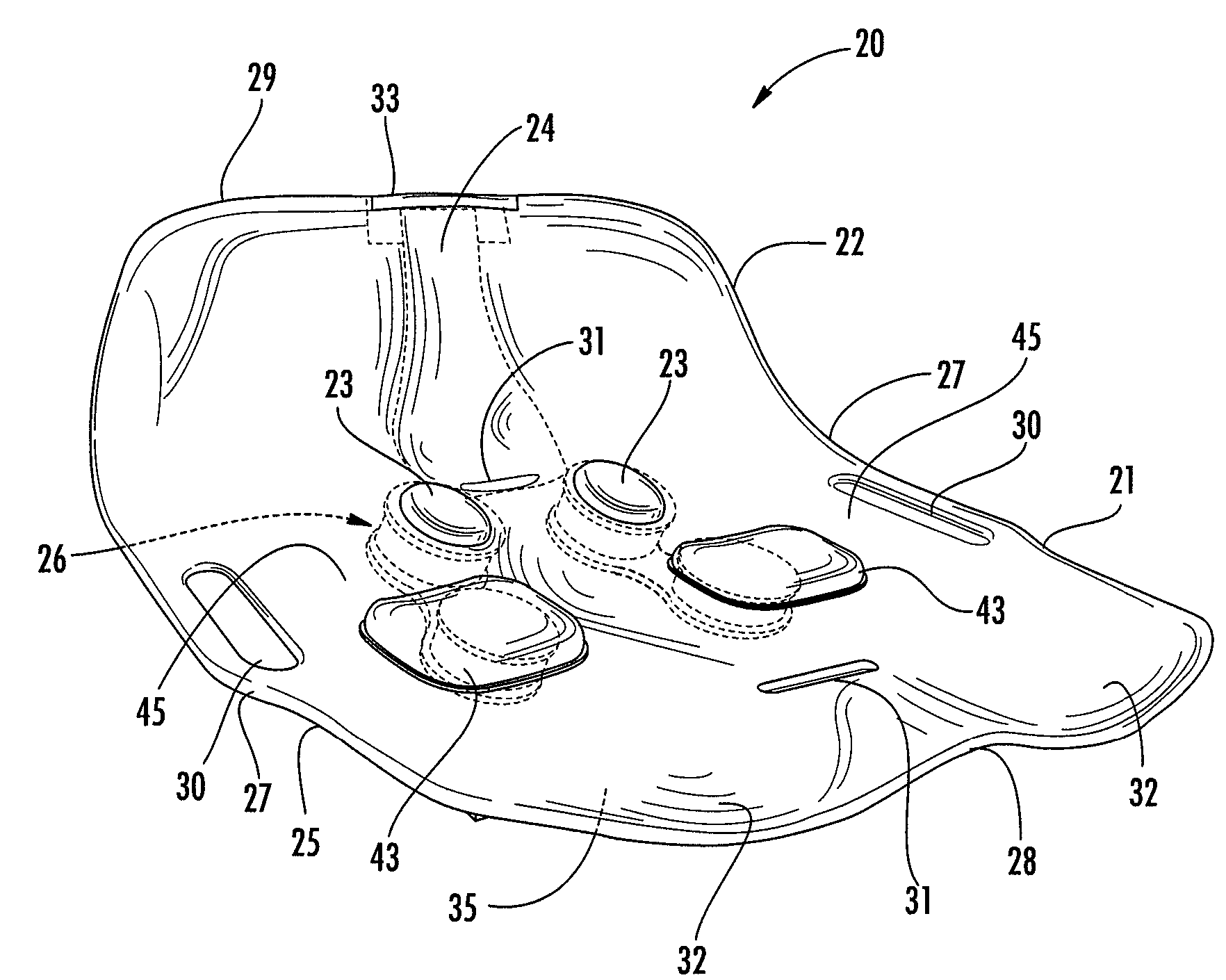
[0023]Generally, the present invention includes a contoured seat 20 or orthotic having a seat surface 21 and a back surface 22 extending at an angle from the seat surface, as shown in FIG. 1. Defined in the seat surface 21 is a pair of spaced mounds or protrusions, such as a pair of ovals 23 of the illustrated embodiment, extending upwards from the seat surface at areas configured to extend into the piriformis muscles of a sitter. In addition, the contoured seat 20 may include a deep sacrum and coccyx pocket 24...


PUM


Abstract

A contoured seat generally includes a seat surface for supporting the thighs and buttocks of a sitter and a back surface for supporting the lower back of a sitter. Defined by the seat surface are a pair of bilateral, spaced protrusions that are positioned to extend into performs musculature of the sitter. Preferably, the seat surface is inclined at a 5° to 15°, and more preferably a 7.5°, angle to induce forward pelvic tilt in conjunction with lower lumbar support of a forward angle of the back surface. The seat and back surfaces may define a sacral-coccyx pocket that has a depth that varies, along its proximal-distal path to allow for sacral stabilization. The sacral-coccyx pocket preferably is relatively narrow and deep proximally and flares as it extends in the distal direction. A reinforcing ridge may extend across a top edge of the sacral-coccyx pocket to provide additional support.

Description

CROSS-REFERENCE TO RELATED APPLICATIONS[0001]This application claims the benefit of U.S. Provisional Patent Application No. 60 / 717,408, filed Sep. 15, 2005, which is incorporated herein by reference in its entirety.BACKGROUND OF THE INVENTION[0002]1. Field of the Invention[0003]The present invention is related to orthopedic supports, and in particular supportive seats that seek to mediate or avoid orthopedic injuries.[0004]2. Description of Related Art[0005]Lower back injuries (chronic and acute) are a massive problem in the United States, leading to significant economic costs due to the expense of treatment and the lost productivity of workers. These injuries are especially prevalent in workers that have intermittent labor duties between which they spend long times in a seated position. For example, truck drivers oftentimes spend eight or more hours per day seated during driving and then must immediately begin unloading upon reaching a destination. This not only causes back injurie...

Claims


Application Information

Patent Timeline
Patent Type & Authority Patents(United States)
IPC IPC(8): A47C7/02
CPCA47C7/022A47C7/029
Inventor GREGORY, MATTHEW WAYNEGADDIS, MARSHALL DEAN
Owner GREGORY MATTHEW WAYNE
Learn More