Planing and polishing machine

a polishing machine and polishing technology, applied in the direction of grinding drives, flat surface machines, manufacturing tools, etc., can solve the problems of reducing the working precision of the machine, unable to be whirled as quickly as needed to sufficiently smooth, etc., to achieve high precision of planning and polishing, boosted dynamic efficiency, and powerful cutting

Inactive Publication Date: 2009-10-27
CHUANG BOR YANN
View PDF13 Cites 9 Cited by
  • Summary
  • Abstract
  • Description
  • Claims
  • Application Information

AI Technical Summary

Benefits of technology

[0006]The object of this invention is to offer a planing and polishing machine able to drive its blade and its grinding wheel to rotate in different speeds so as to enhance dynamic efficiency and machining precision.
[0008]According to the characteristics mentioned above, as the driving motor is turned on to draw the first driving element and the second driving element, the blade and the grinding roller are to be independently driven to simultaneously rotate in different speeds, enabling the blade to powerfully cut off the surface of a workpiece, achieving a boosted dynamic efficiency and a high precision of planning and polishing.

Problems solved by technology

However, the blade 6 is indirectly driven by the grinding wheels 7, it can't be whirled as quick as needed to sufficiently plane, possible to lower its working precision.

Method used


Image

  • Planing and polishing machine
  • Planing and polishing machine
  • Planing and polishing machine

Examples


Embodiment Construction

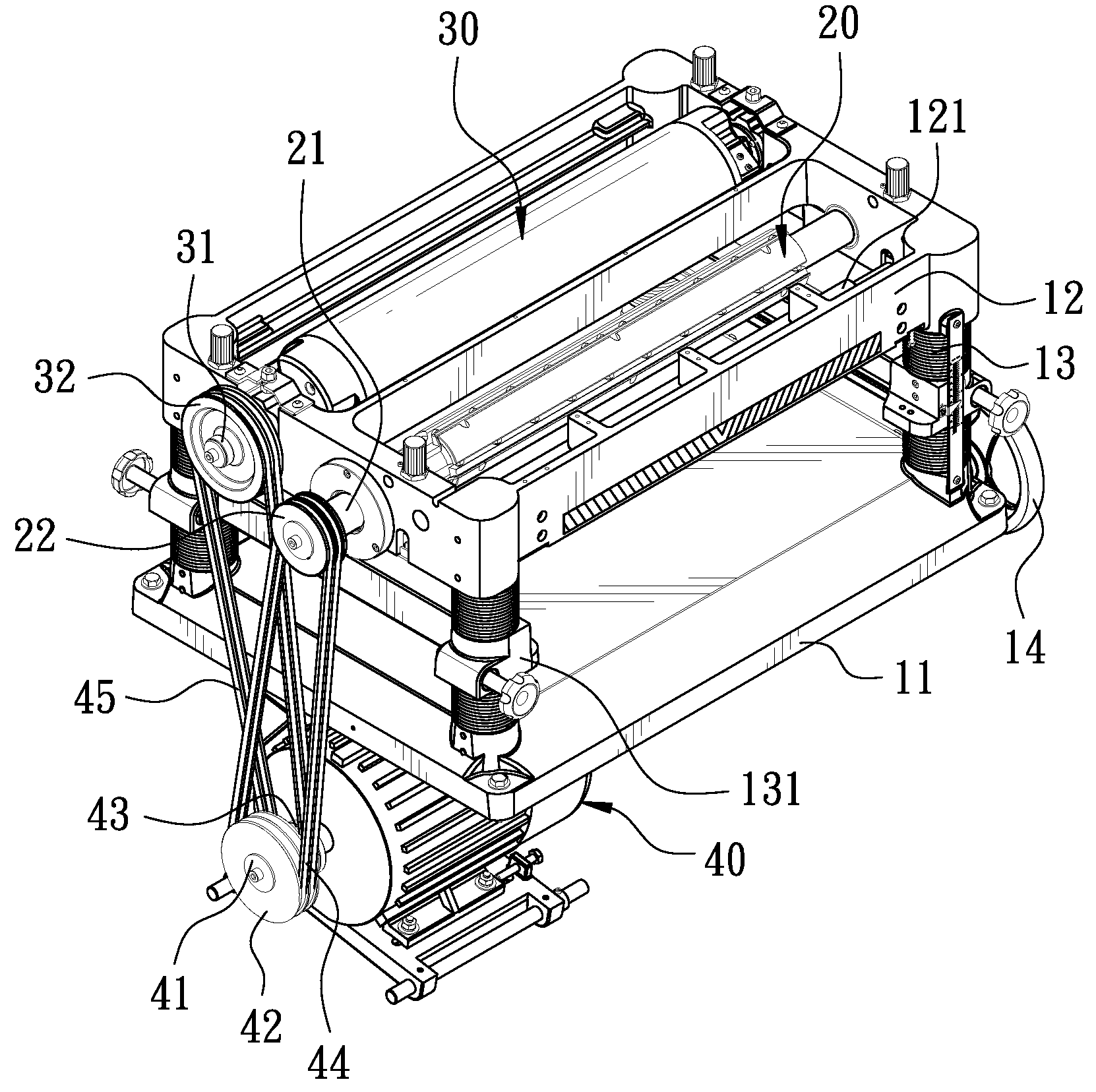
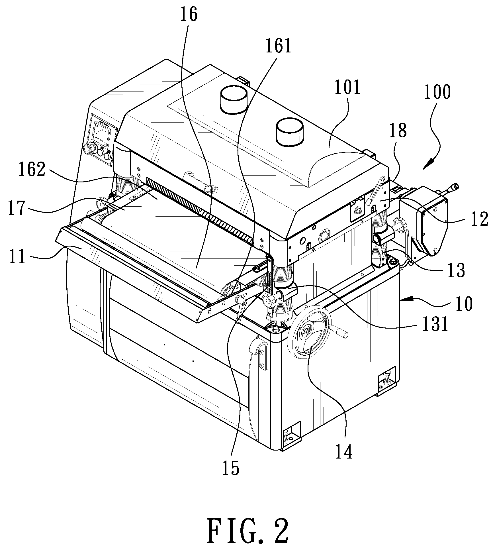
[0015]As shown in FIGS. 2 and 3, a preferred embodiment of a planing and polishing machine 100 in the present invention is covered by a hood 101, provided with a base 10, a blade 20, a grinding wheel 30 and a driving motor 40.

[0016]The base 10 is formed as a platform, employed to keep the planing and polishing machine 100 stably positioned on it. Sequentially installed above the base 10 are an intermediate base 11 and an upper base 12 formed as a rectangular frame. The intermediate base 11 is installed on the base 10, with each of its corners fixed with an adjusting screw 13 that is fixedly positioned on the base 10, used to adjust the distance between the intermediate base 11 and the upper base 12 so as to enable a workpiece properly planed. A transverse rod 131 is axially linked between two adjacent adjusting screws 13 at two sides of the intermediate base 11 respectively. An adjusting wheel 14 is installed at one side of one of the adjusting screws 13 for altering the level of th...


PUM


Abstract

A planning and polishing machine includes a base, an intermediate base installed with a conveying device for laying a workpiece, and an upper base pivotally fixed with at least a planer and a grinding roller. A driving motor is installed below the conveying device, with its shaft engaged with a first driving wheel and a second driving wheel with different diameters. The first driving wheel and the blade are mounted by a first driving element, and the second driving wheel and the grinding roller are mounted by a second driving element. When the driving motor is turned on to draw the first driving element and the second driving element, the blade and the grinding roller are to be meanwhile driven to rotate in different rotating speeds, enabling the blade to powerfully plane the surface of a wood, achieving a high precision and efficiency of planning and polishing.

Description

BACKGROUND OF THE INVENTION[0001]1. Field of the Invention[0002]This invention relates to a planing and polishing machine.[0003]2. Description of the Prior Art[0004]Commonly, woods are planed and polished respectively by a conventional planer and a conventional polisher. The polisher can only grind off slightly and the planer can merely plane so roughly that an additional grinder is ever needed for further grinding. As shown in FIG. 1, a conventional planing and polishing machine mainly includes a base 1, an intermediate base 2, a conveying device 3, an upper base 4 and a driving motor 5. Transversely and pivotally connected on the upper base 4 are a blade 6 and two grinding wheels 7, with one end of a shaft 8 of each of the grinding wheels 7 extended outside the upper base 4. The shafts 8 and a driving shaft 5A of the driving motor 5 are mounted by a first belt (B). The blade 6 has one end of its shaft 9 extended outside the upper base 4 and linked with the shaft 8 of the adjacent ...

Claims


Application Information

Patent Timeline
Patent Type & Authority Patents(United States)
IPC IPC(8): B24B49/00
CPCB24B7/28B27C1/14B27C1/04B24B47/12
Inventor CHUANG, BOR-YANN
Owner CHUANG BOR YANN
Why Eureka
Try Eureka