Electron optical component

a technology of optical components and electrons, applied in the field of electron optics, can solve the problems of difficult to transfer electrons from the imaging lens system, low energy resolution, and inability to image high-energy electrons with chemical specificity, and achieve the effect of improving the spatial resolution of magnetic projection

Inactive Publication Date: 2009-10-27
BROWNING RAYMOND
View PDF12 Cites 5 Cited by
  • Summary
  • Abstract
  • Description
  • Claims
  • Application Information

AI Technical Summary

Benefits of technology

[0010]It is an object of the invention to provide an electron optical component used to improve the spatial resolution in magnetic projection

Problems solved by technology

Although this is a straightforward technique the problem is that it is intrinsically noisy and of low energy resolution.
However, there is a problem with this approach.
It is difficult to transfer the electrons from the imaging lens system into the energy analysis system and preserve the image.
Hirose used a pulsed X-ray source and a pulsed electronic gating method to only image slowe

Method used


Image

  • Electron optical component
  • Electron optical component
  • Electron optical component

Examples


Embodiment Construction

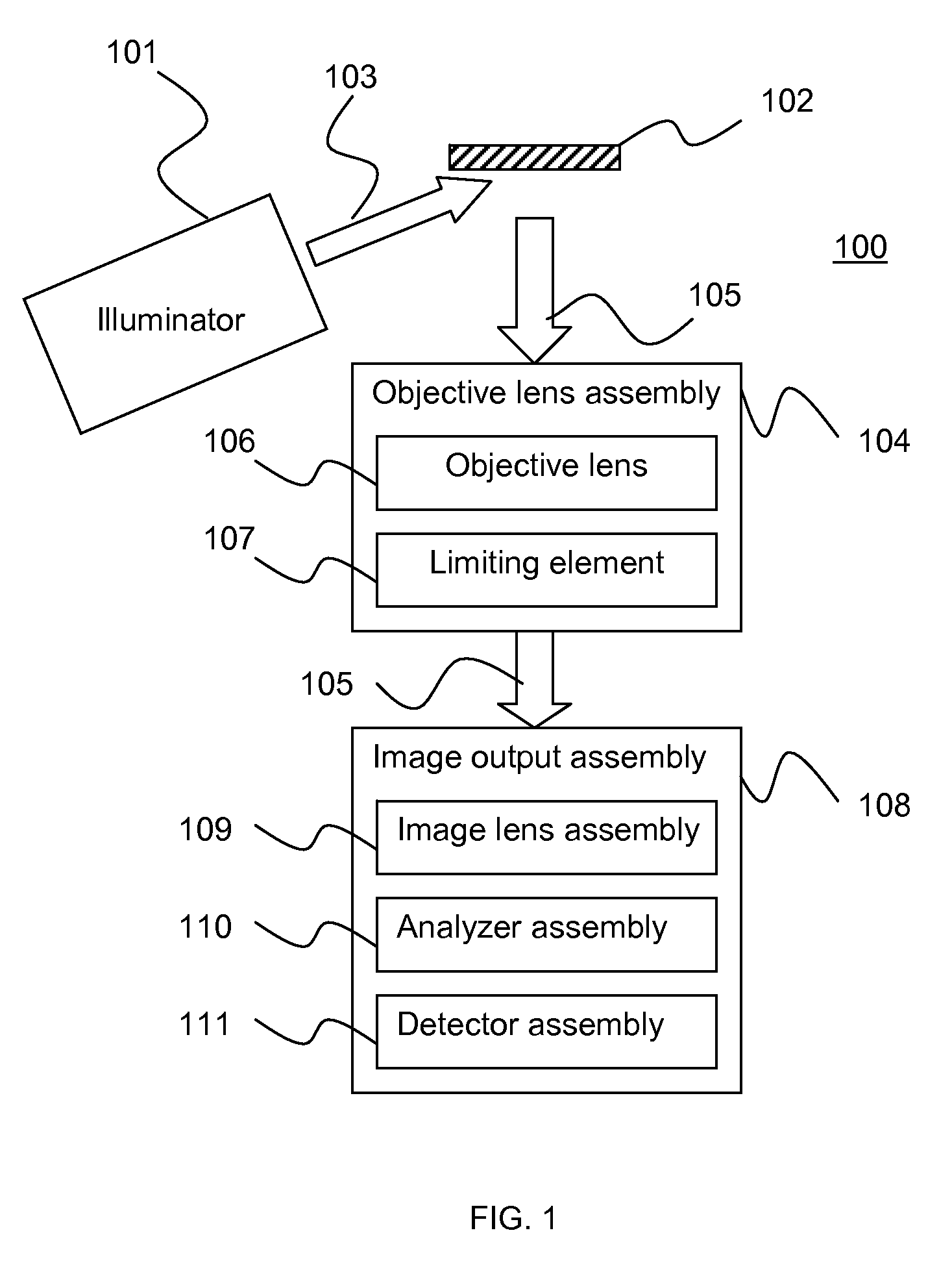
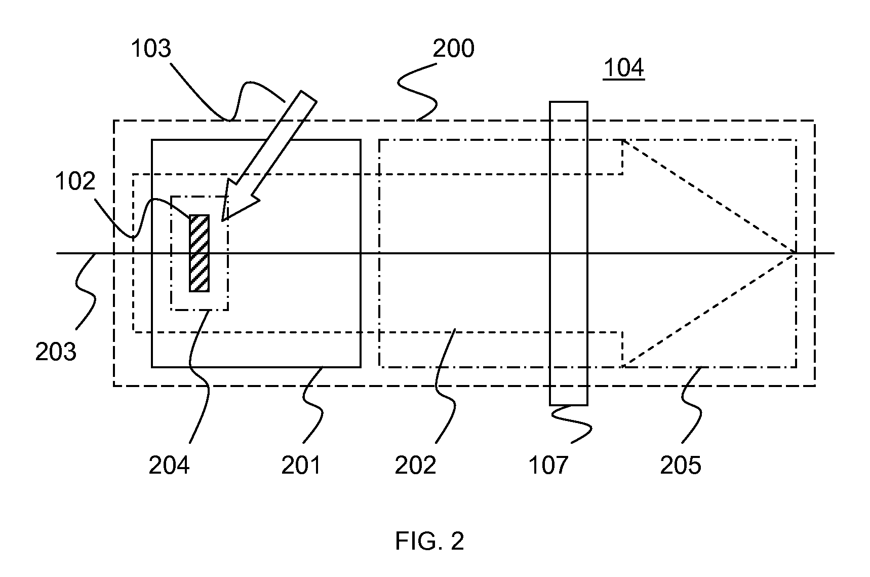
[0039]Referring to FIGS. 1 through 23, wherein like reference numerals refer to like components in the various views, there is illustrated therein a new and improved electron optical apparatus.

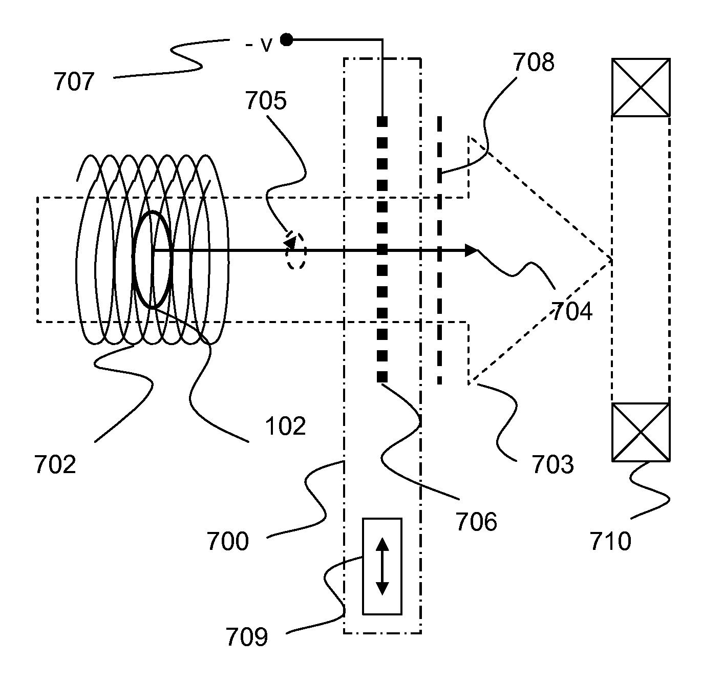
[0040]It is an object of the invention to provide a projection electron lens apparatus with a high spatial resolution. It is a further object of the invention to provide a high spatial resolution photoelectron microscope apparatus. It is a further object of the invention to provide a high spatial resolution photoelectron microscope apparatus with energy resolved imaging. It is a further object of the invention to provide an electron optical device that limits the cyclotron orbit radii within a magnetic field. It is a further object of the invention to provide a projection magnetic field using a permanent magnet device.

[0041]The invention described herein is contained in several functional elements and sub-elements individually and combined together to form the elements of an electron microscop...


PUM


Abstract

An electron optical component used to improve the spatial resolution in magnetic projection electron lenses or other electron optical devices by filtering the cyclotron orbit radii of electron trajectories in the lens magnetic field.

Description

STATEMENT REGARDING FEDERALLY SPONSORED RESEARCH OR DEVELOPMENT[0001]This invention was made with Government support under SB1341-07CN-0042 awarded by the National Institute of Standards and Technology. The Government has certain rights in the invention.TECHNICAL FIELD[0002]The present invention relates generally to electron optics, and more particularly to electron microscopes, and more particularly to a photoelectron microscope, and more particularly to a photoelectron microscope with a magnetic projection lens, and more particularly to a magnetic projection lens having a cyclotron orbit radii filter, and more particularly to a cyclotron orbit radii filter being composed of a grid having apertures defining the spatial resolution of the projection lens. In another aspect of the invention the magnetic projection lens has a magnetic field which is terminated by a magnetic plate with an aperture. In another aspect of the invention the electrons exiting the magnetic projection lens thr...

Claims


Application Information

Patent Timeline
IPC IPC(8): H01J49/20
CPCH01J37/05H01J37/285H01J2237/2855
Inventor BROWNING, RAYMOND
Owner BROWNING RAYMOND
Why Eureka
Try Eureka