Extreme ultra violet light source device
a light source device and ultra violet technology, applied in the field of ultra violet light source devices, can solve the problems of reducing the output of euv light, reducing the vacuum or cleanness in the plasma generation chamber, and difficult to keep inside the plasma generation chamber at a high degree of vacuum, etc., to achieve the effect of high vacuum or cleanness in the second chamber, high vacuum or cleanness, and economical and simple structur
- Summary
- Abstract
- Description
- Claims
- Application Information
AI Technical Summary
Benefits of technology
Problems solved by technology
Method used
Image
Examples
first embodiment
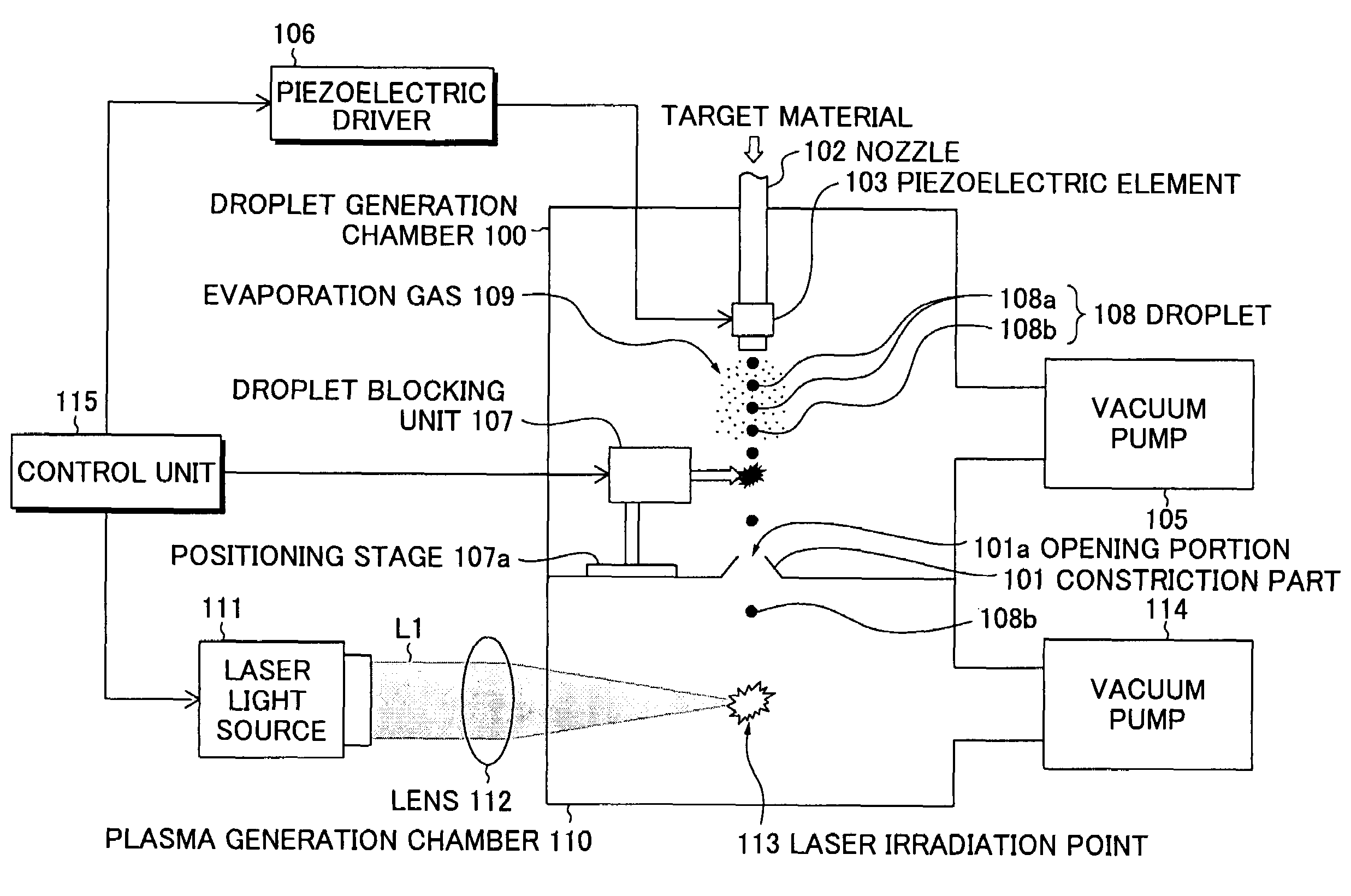
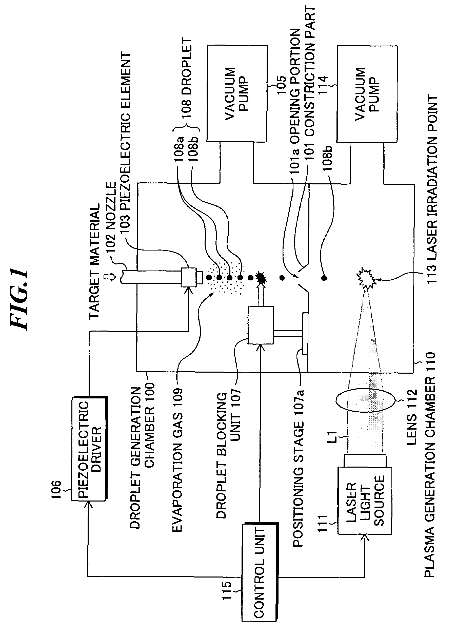
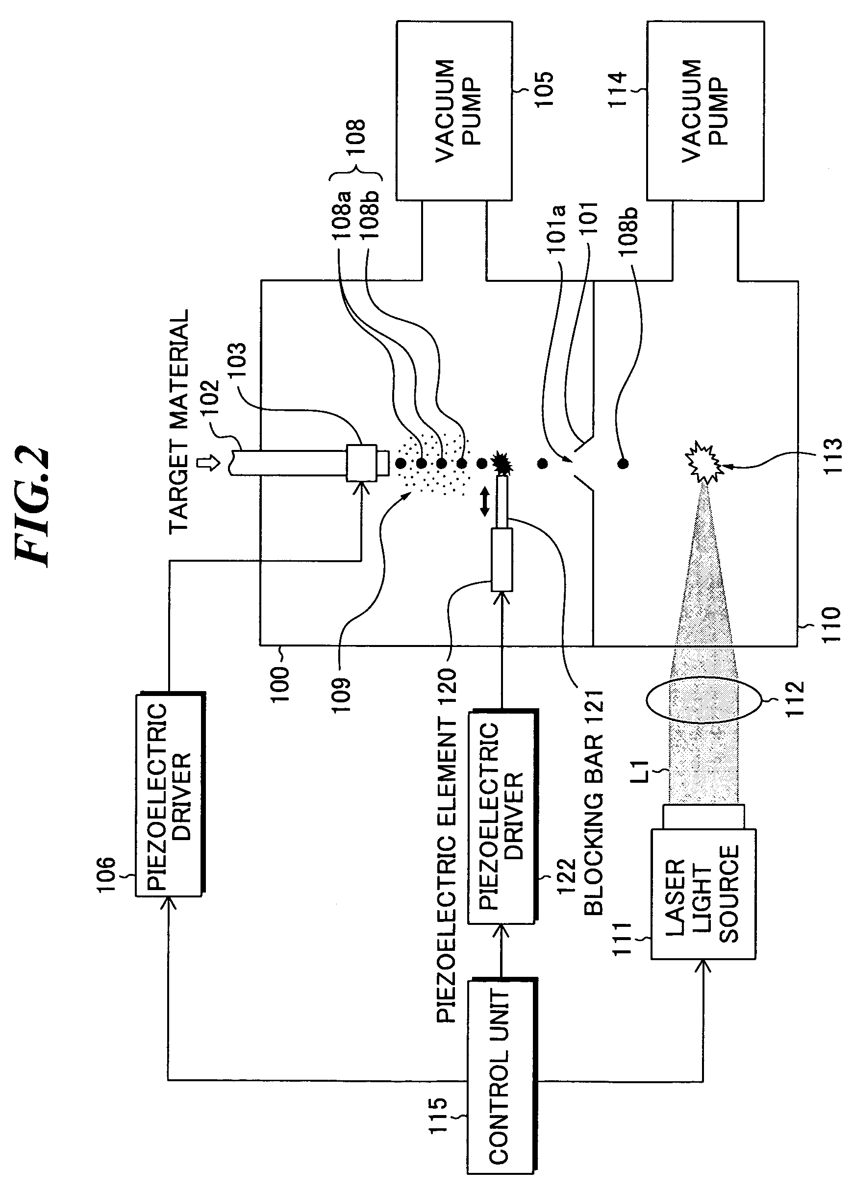
[0068]FIG. 2 is a schematic diagram showing a structure of the EUV light source device according to the present invention. In the EUV light source device, the droplet blocking unit 107 as shown in FIG. 1 is constructed by employing a piezoelectric element. Other components are the same as those in the EUV light source device as shown in FIG. 1.
[0069]As shown in FIG. 2, the EUV light source device includes a piezoelectric element 120 provided with a blocking bar 121, a piezoelectric driver 122 for generating a drive signal to be provided to the piezoelectric element 120. In this embodiment, a piezoelectric element of an actuator type is used. Generally, a piezoelectric element of an actuator type is an element for expanding and contracting on the direction according to polarity of applied voltage, and characterized by quick time response to a drive signal. The piezoelectric driver 122 generates a drive signal at a predetermined time interval for expanding or contracting the piezoelec...
second embodiment
[0073]FIG. 4 is a schematic diagram showing the structure of the EUV light source device according to the present invention. In the EUV light source device, the droplet blocking unit 107 shown in FIG. 1 employs a structure in which a plurality of piezoelectric elements are used. Incidentally, in FIG. 4, an example in which two piezoelectric elements are used is shown, however, it may also be possible to use three or more piezoelectric elements. Other structures are the same as the EUV light source device shown in FIG. 1.
[0074]As shown in FIG. 4, the EUV light source device includes a piezoelectric element 130 of an actuator type provided with a blocking bar 131, a piezoelectric element 132 of an actuator type provided with a blocking bar 133, and a piezoelectric driver 134 for generating a drive signal to be supplied to the piezoelectric elements 130 and 132, respectively. The position and length of the blocking bars 131 and 133 in the piezoelectric elements 130 and 132 are adjusted...
third embodiment
[0078]FIG. 5 is a schematic diagram showing the structure of the EUV light source device according to the present invention. The present embodiment shows another concrete example in which a piezoelectric element is used as the droplet blocking unit 107 shown in FIG. 1. Other structure is the same as that of the EUV light source device shown in FIG. 1.
[0079]The EUV light source device shown in FIG. 5 includes a piezoelectric element 140 of an actuator type provided with a blocking part 141 and a piezoelectric driver 142 for generating a drive signal to be supplied to the piezoelectric element 140. The blocking part 141 includes a blocking bar 141a the lengthwise side of which is in the direction of the column of droplets. The blocking bar 141a collides with a plurality of droplets 108a when the piezoelectric element 141 expands and contracts once to break the droplets 108a or change the orbit thereof. In this manner, by breaking the plurality of droplets 108a at a time, the drive fre...
PUM
 Abstract
Description
Claims
Application Information
 - R&D
- Intellectual Property
- Life Sciences
- Materials
- Tech Scout
- Unparalleled Data Quality
- Higher Quality Content
- 60% Fewer Hallucinations
Browse by: Latest US Patents, China's latest patents, Technical Efficacy Thesaurus, Application Domain, Technology Topic, Popular Technical Reports.
© 2025 PatSnap. All rights reserved.Legal|Privacy policy|Modern Slavery Act Transparency Statement|Sitemap|About US| Contact US: help@patsnap.com


