Wash-target holder, and wash-target holding apparatus, washing apparatus and method for washing wash-target using the same
a technology for washing target and holding apparatus, which is applied in the direction of cleaning process and apparatus, cleaning using liquids, chemistry apparatus and processes, etc., can solve the problems of deteriorating cleanness, inconvenient generation, and solvent of washing liquid cannot be easily removed from the wash-target after completing the washing. , to achieve the effect of improving washing efficiency and cleaning
- Summary
- Abstract
- Description
- Claims
- Application Information
AI Technical Summary
Benefits of technology
Problems solved by technology
Method used
Image
Examples
first embodiment
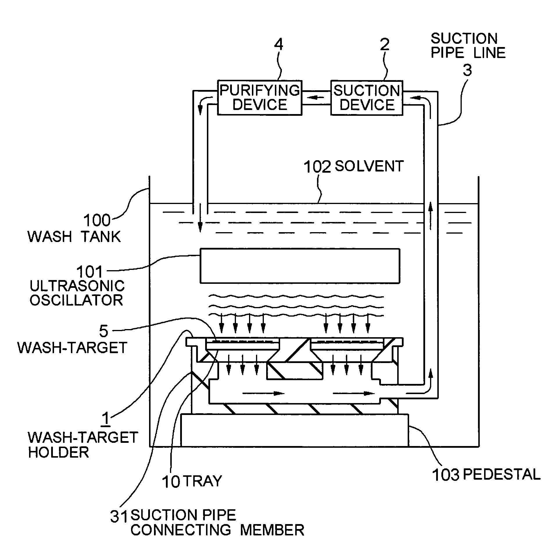
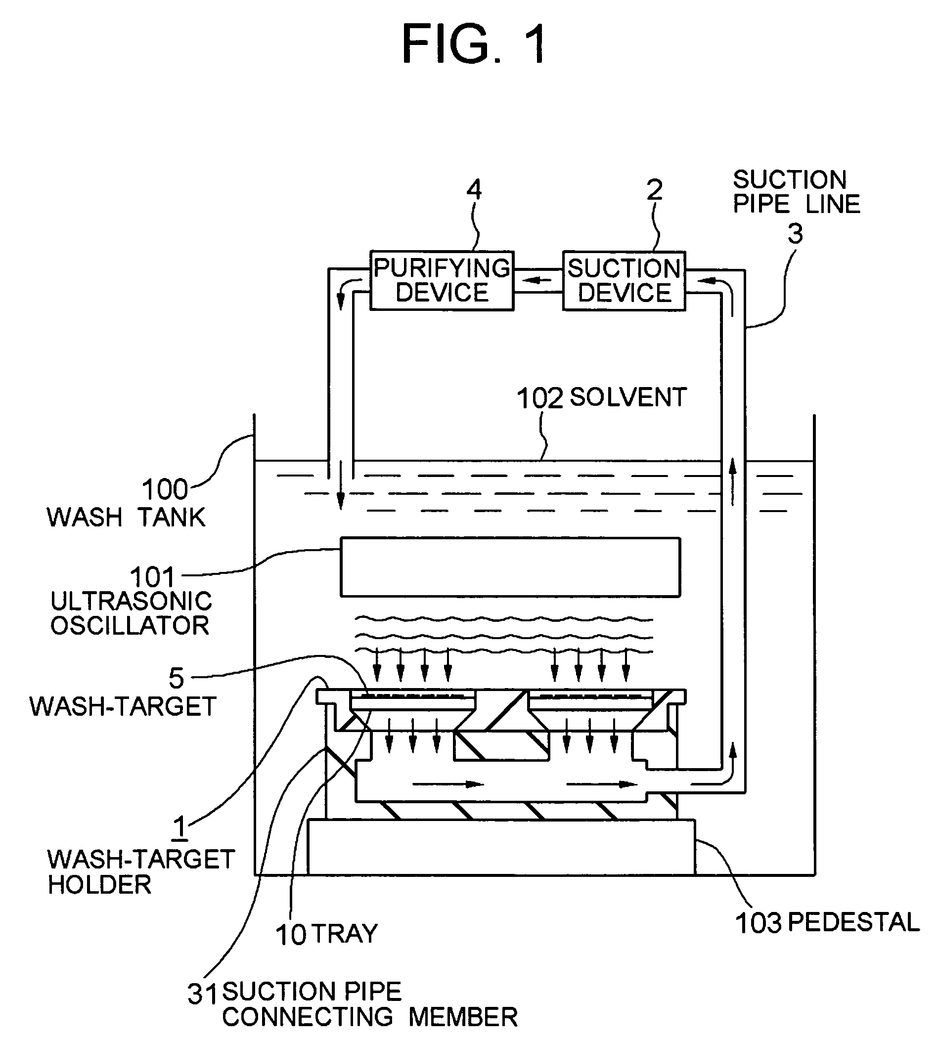
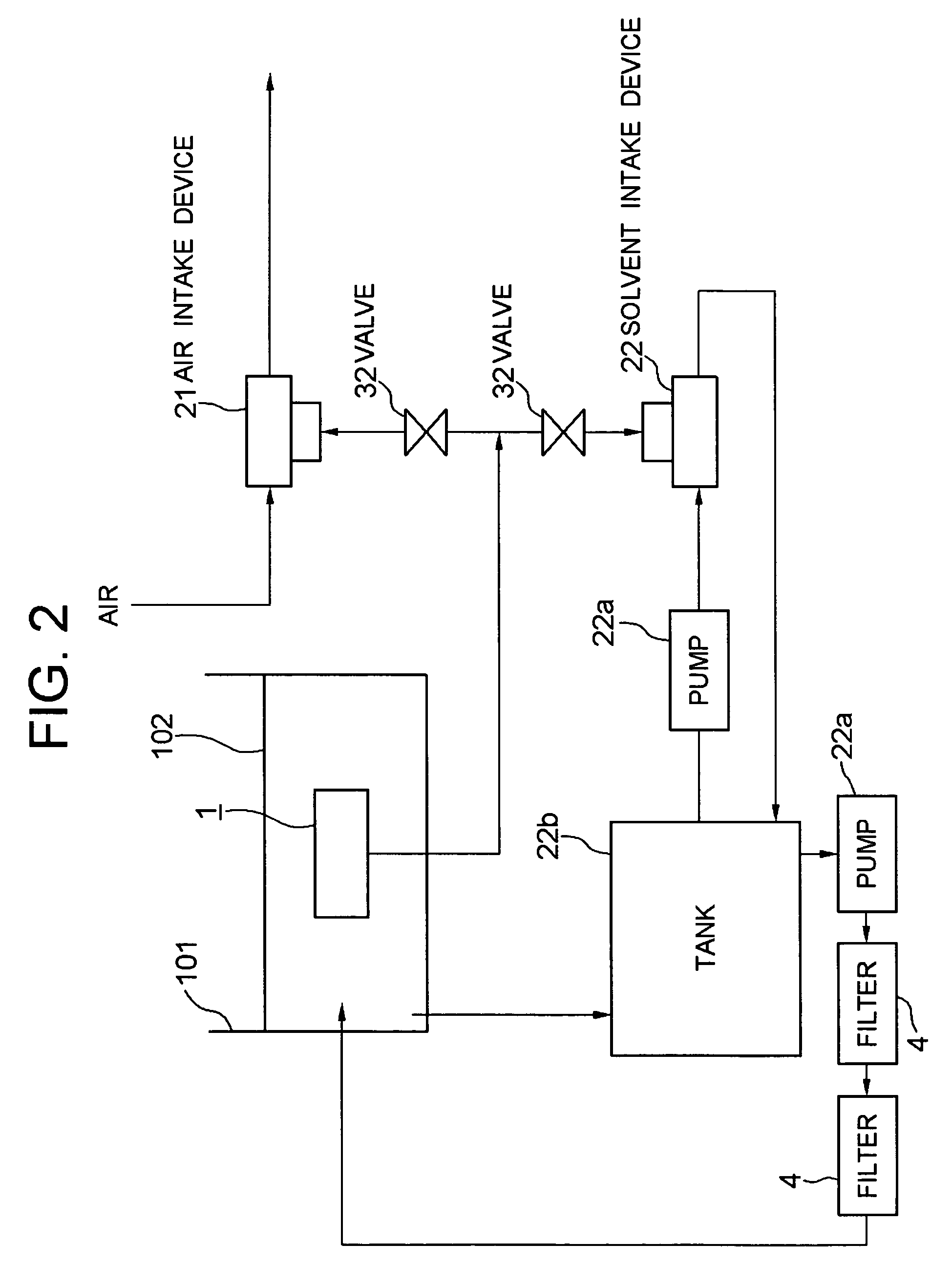
[0050]A first embodiment of the present invention will be described by referring to FIG. 1-FIG. 9. FIG. 1 and FIG. 2 are illustrations for showing the schematic structure of a washing apparatus for washing a wash-target. FIG. 3-FIG. 7 are illustrations for showing the structure of a wash-target holder. FIG. 8 and FIG. 9 are illustrations for showing the action of the washing apparatus.
(Structure)
Washing Apparatus
[0051]Referring to FIG. 1, the overall structure of the washing apparatus for washing a wash-target will be described. The washing apparatus comprises: a wash tank 100 to which a solvent 102 for washing a wash-target 5 is filled; wash-target holding apparatuses (1, 2, etc.) for holding a magnetic head slider 5 as the wash-target; circulators (3, 4, etc.) (circulating devices) for circulating the solvent 102; and a washing device 101 for washing the wash-target within the wash tank 100. First, the configuration thereof will be described briefly. Then, each structure will be d...
second embodiment
[0094]Next, a second embodiment of the present invention will be described by referring to FIG. 10 and FIG. 11. FIG. 10 is a schematic diagram for showing the structure of the washing apparatus according to this embodiment, and FIG. 11 is an illustration for showing the structure of the tray.
[0095]The washing apparatus of this embodiment uses a roll brush 104 (a brush washing device) as a washing device, which washes the magnetic head slider 5 as the wash-target disposed on the tray 10 by brushing it using the roll brush 104. In other words, the washing apparatus of this embodiment comprises the structure similar to that of the washing apparatus disclosed in the first embodiment but with the roll brush 104 as the washing equipment instead of the ultrasonic oscillator 101.
[0096]Specifically, as shown in FIG. 10 which illustrates the washing apparatus schematically, the wash-target holder 1 to which the suction pipe connecting member 31 of the suction pipe line 3 is connected is place...
third embodiment
[0100]A third embodiment of the present invention will be described by referring to FIG. 12. FIG. 12 is a schematic diagram for showing the structure of the washing apparatus of this embodiment.
(Structure)
[0101]The washing apparatus of this embodiment uses a micro-bubble generator 105 (micro-bubble washing device) as a washing device, which washes the wash-target 5 by micro-bubbles 105a generated by the micro-bubble generator 105. The structure of the washing apparatus according to this embodiment will be described in detail hereinafter.
[0102]As shown in FIG. 12, in the washing apparatus of this embodiment, the wash-target holing apparatuses 1, 2, i.e. the wash-target holder 1, is soaked into the wash tank 100 in a reversed direction of the above-described direction. In other words, the wash-target holder 1 is placed so that the held wash-target 5 faces downwards, and it is supported within the wash tank 100 by a supporting mechanism, not shown. The micro-bubble generator 105 is dis...
PUM
 Abstract
Description
Claims
Application Information
 - R&D
- Intellectual Property
- Life Sciences
- Materials
- Tech Scout
- Unparalleled Data Quality
- Higher Quality Content
- 60% Fewer Hallucinations
Browse by: Latest US Patents, China's latest patents, Technical Efficacy Thesaurus, Application Domain, Technology Topic, Popular Technical Reports.
© 2025 PatSnap. All rights reserved.Legal|Privacy policy|Modern Slavery Act Transparency Statement|Sitemap|About US| Contact US: help@patsnap.com


