Extreme ultra violet light source device

a light source device and ultra violet technology, applied in the field of ultra violet light source devices, can solve the problems of reducing the output of euv light, reducing the vacuum or cleanness in the plasma generation chamber, and difficult to keep inside the plasma generation chamber at a high degree of vacuum, etc., to achieve the effect of high vacuum or cleanness in the second chamber, high vacuum or cleanness, and economical and simple structur

Active Publication Date: 2007-07-26
GIGAPHOTON
View PDF12 Cites 73 Cited by
  • Summary
  • Abstract
  • Description
  • Claims
  • Application Information

AI Technical Summary

Benefits of technology

[0018]The present invention has been achieved in view of the above-mentioned problems. An object of the present invention is to improve a degree of vacuum or cleanness in a plasma generation chamber in the EUV light source device while the construction is simplified.
[0020]According to the present invention, by blocking droplets, which are not irradiated with a laser beam, from among the generated droplets, excessive droplets are prevented from being introduced into the second chamber, and therefore, a degree of vacuum or cleanness in the second chamber can be kept high with an economical and simple structure. As a result, generation efficiency of extreme ultra violet light emitted from the target material turned into a plasma state can be improved economically.

Problems solved by technology

However, in the case where only the vacuum pump 5 is provided to the plasma generation chamber 2, it is difficult to keep inside of the plasma generation chamber 2 at a high degree of vacuum.
However, even if the buffer droplets act for absorbing radiation from the ionized target droplet, a degree of vacuum or cleanness in the plasma generation chamber is decreased due to the buffer droplets, which causes reduced output of the EUV light.
As a result, also in the EUV light source device, a degree of vacuum in the plasma generation chamber 2 cannot be kept at a high degree of vacuum, and the generated EUV light is absorbed, which causes reduced output of the EUV light.
Therefore, it is also difficult to keep the pressure at a high degree of vacuum in the plasma generation chamber 2 or to protect components such as a mirror in the chamber from the gasified target material.
Further, three chambers and three vacuum pumps become required, which makes the system large and complicated.
The above-mentioned influence of the target turned into plasma affecting the adjacent targets becomes problem not only in the case where the target material is in a gas state at a room temperature, for example, xenon, but also in the case where the target material is in a solid state or a liquid state including solid at a room temperature, for example, molten metal of stannum or lithium, mixture in which minute metal particles of stannum, stannum oxide, copper or the like are dispersed into water or alcohol, or ionic solution in which lithium fluoride or lithium chloride is dissolved into water.
Those target materials may evaporate by being affected by heat of plasma, once gasified metal particles contaminate components such as a mirror in the chamber, further degrade performance of the EUV light source device.

Method used


Image

  • Extreme ultra violet light source device
  • Extreme ultra violet light source device
  • Extreme ultra violet light source device

Examples


first embodiment

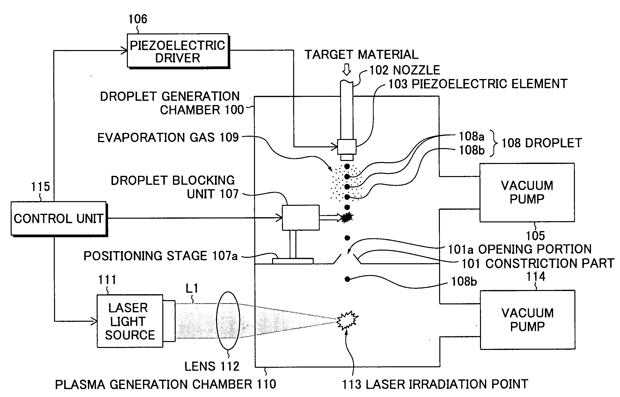
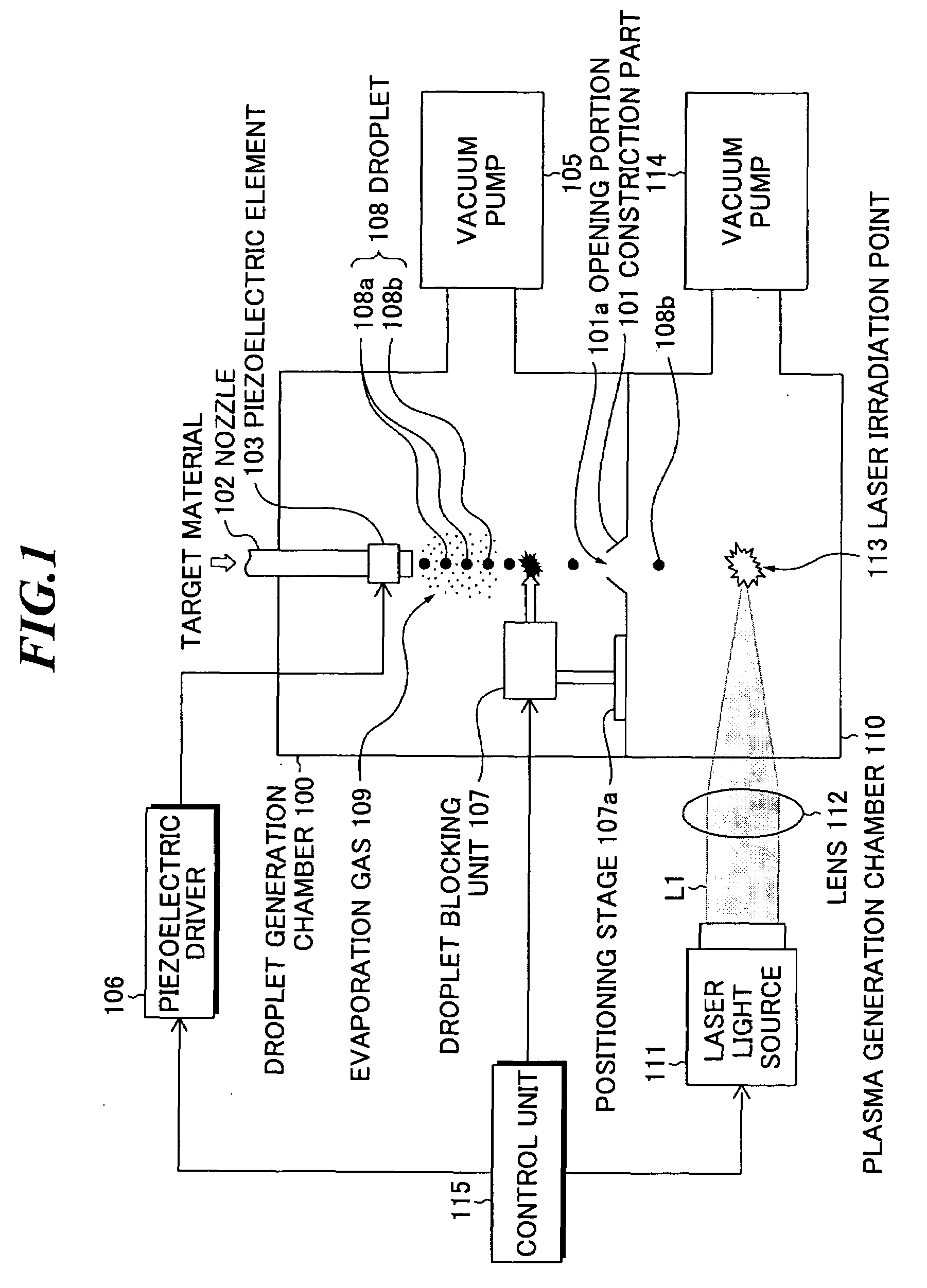
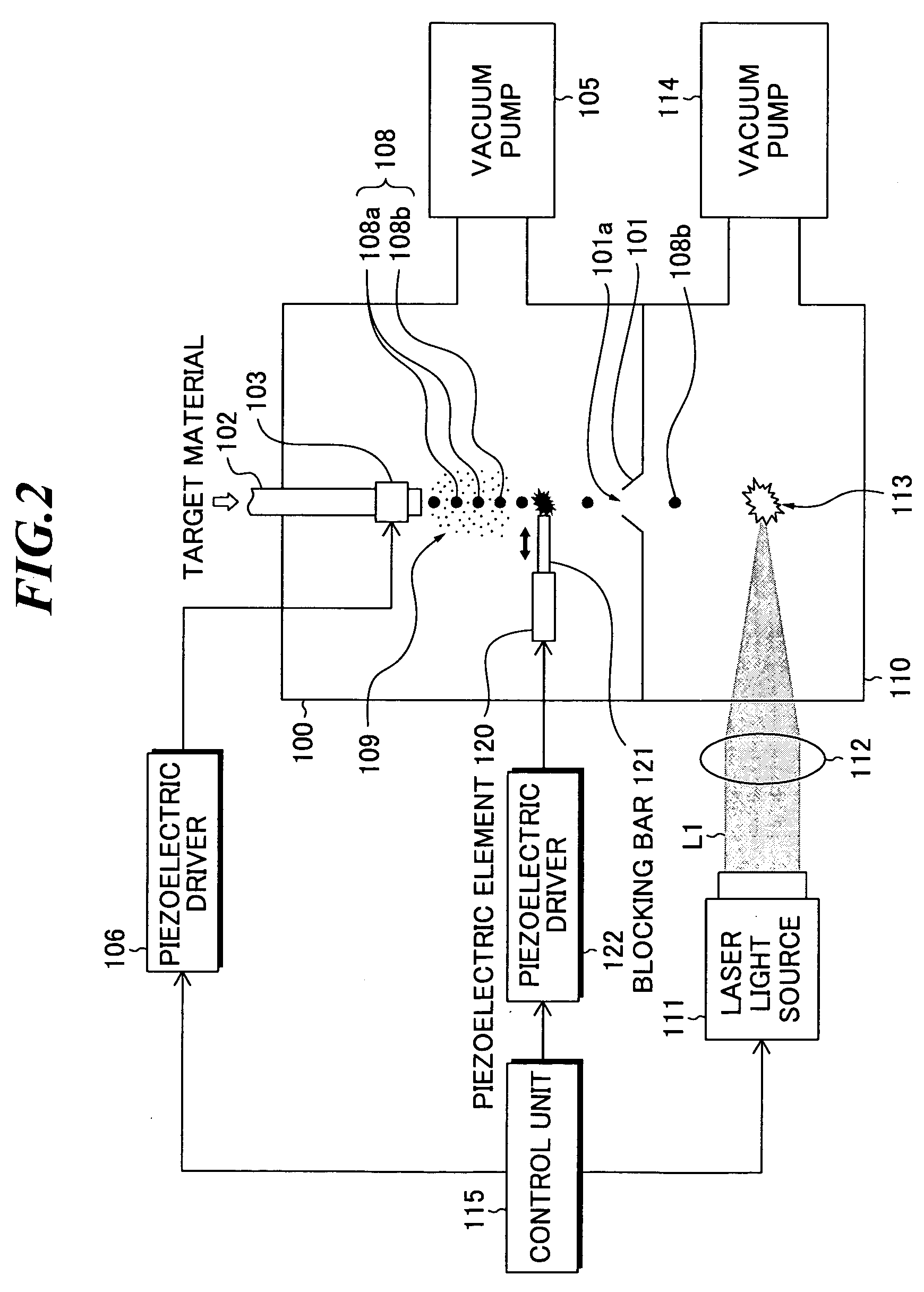
[0067]FIG. 2 is a schematic diagram showing a structure of the EUV light source device according to the present invention. In the EUV light source device, the droplet blocking unit 107 as shown in FIG. 1 is constructed by employing a piezoelectric element. Other components are the same as those in the EUV light source device as shown in FIG. 1.

[0068]As shown in FIG. 2, the EUV light source device includes a piezoelectric element 120 provided with a blocking bar 121, a piezoelectric driver 122 for generating a drive signal to be provided to the piezoelectric element 120. In this embodiment, a piezoelectric element of an actuator type is used. Generally, a piezoelectric element of an actuator type is an element for expanding and contracting on the direction according to polarity of applied voltage, and characterized by quick time response to a drive signal. The piezoelectric driver 122 generates a drive signal at a predetermined time interval for expanding or contracting the piezoelec...

second embodiment

[0072]FIG. 4 is a schematic diagram showing the structure of the EUV light source device according to the present invention. In the EUV light source device, the droplet blocking unit 107 shown in FIG. 1 employs a structure in which a plurality of piezoelectric elements is used. Incidentally, in FIG. 4, an example in which two piezoelectric elements are used is shown, however, it may also be possible to use three or more piezoelectric elements. Other structures are the same as the EUV light source device shown in FIG. 1.

[0073]As shown in FIG. 4, the EUV light source device includes a piezoelectric element 130 of an actuator type provided with a blocking bar 131, a piezoelectric element 132 of an actuator type provided with a blocking bar 133, and a piezoelectric driver 134 for generating a drive signal to be supplied to the piezoelectric elements 130 and 132, respectively. The position and length of the blocking bars 131 and 133 in the piezoelectric elements 130 and 132 are adjusted ...

third embodiment

[0077]FIG. 5 is a schematic diagram showing the structure of the EUV light source device according to the present invention. The present embodiment shows another concrete example in which a piezoelectric element is used as the droplet blocking unit 107 shown in FIG. 1. Other structure is the same as that of the EUV light source device shown in FIG. 1.

[0078]The EUV light source device shown in FIG. 5 includes a piezoelectric element 140 of an actuator type provided with a blocking part 141 and a piezoelectric driver 142 for generating a drive signal to be supplied to the piezoelectric element 140. The blocking part 141 includes a blocking bar 141a the lengthwise side of which is in the direction of the column of droplets. The blocking bar 141a collides with a plurality of droplets 108a when the piezoelectric element 141 expands and contracts once to break the droplets 108a or change the orbit thereof. In this manner, by breaking or so the plurality of droplets 108a at a time, the dri...


PUM


Abstract

An EUV (extreme ultra violet) light source device in which a degree of vacuum or cleanness in a plasma generation chamber is improved while the construction is simplified. The device includes: a first chamber; a second chamber connected to the first chamber through an opening portion; a target supplier that supplies a target material into the first chamber; a droplet generating unit that generates droplets of the target material of molten metal repetitively dropping based on the target material supplied by the target supplier; a blocking unit that prevents the droplets of the target material generated by the droplet generating unit from passing through the opening portion; control unit that controls the blocking unit to operate at predetermined timing; a laser light source; and an optical system that leads a laser beam to the droplets of the target material introduced into the second chamber.

Description

BACKGROUND OF THE INVENTION[0001]1. Field of the Invention[0002]The present invention relates to an EUV (extreme ultra violet) light source device for generating extreme ultra violet light by irradiating a target with a laser beam.[0003]2. Description of a Related Art[0004]As semiconductor processes become finer, the photolithography has been making rapid progress to finer fabrication, and, in the next generation, microfabrication of 100 nm to 70 nm, further, microfabrication of 50 nm or less will be required. For example, in order to fulfill the requirement for microfabrication of 50 nm or less, the development of exposure equipment with a combination of an EUV light source of about 13 nm in wavelength and a reduced projection reflective optics is expected.[0005]As the EUV light source, there are three kinds of an LPP (laser produced plasma) type using plasma generated by irradiating a target with a laser beam, a DPP (discharge produced plasma) type using plasma generated by discha...

Claims


Application Information

Patent Timeline
Patent Type & Authority Applications(United States)
IPC IPC(8): G01J3/10
CPCH05G2/005H05G2/003
Inventor NAKANO, MASAKI
Owner GIGAPHOTON
Why Eureka
Try Eureka