

Light-load efficiency improving method and apparatus for a flyback converter
a technology of flyback converter and efficiency improvement, which is applied in the field of flyback converter, can solve the problems of reducing affecting and increasing the switching time of the power switch sw, so as to achieve the effect of improving the efficiency of the flyback converter
- Summary
- Abstract
- Description
- Claims
- Application Information
AI Technical Summary
Benefits of technology
Problems solved by technology
Method used
Image

Examples
Embodiment Construction
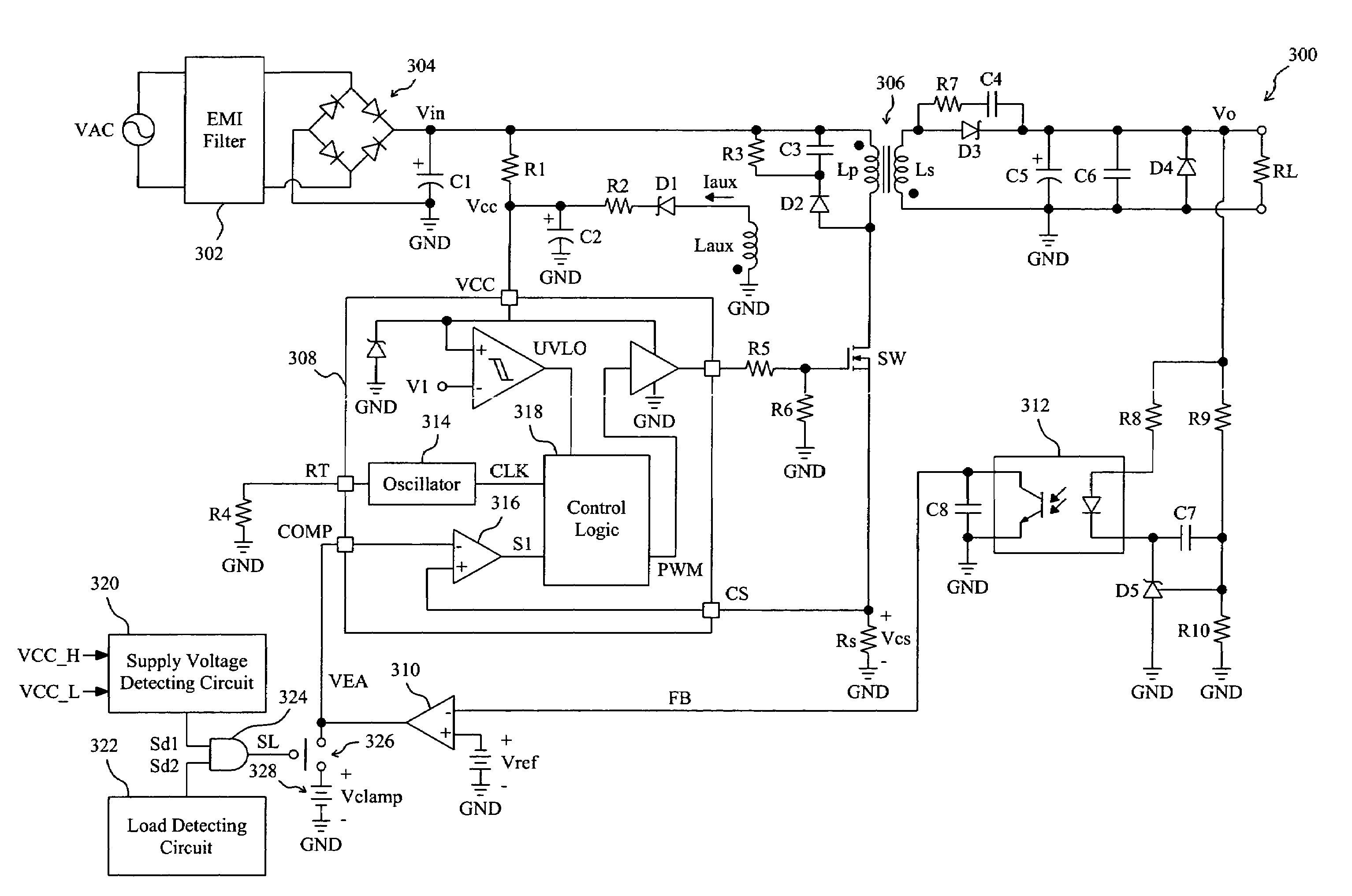
[0016]FIG. 3 shows an embodiment according to the present invention. In a flyback AC-DC converter 300, a line voltage VAC is filtered by an EMI filter 302 and rectified by a bridge rectifier 304 to produce an input voltage Vin, a controller 308 switches a power switch SW such that a transformer 306 transforms the input voltage Vin to an output voltage Vo for a load RL, an auxiliary coil Laux of the transformer 306 provides a current Iaux to charge a capacitor C2 to produce a supply voltage Vcc connected to an input VCC of the controller 308, a photocoupler 312 generates a feedback signal FB by monitoring the output voltage Vo, an error amplifier 310 determines an error signal VEA connected to a feedback input COMP of the controller 308 by comparing the feedback signal FB with a reference voltage Vref, a switch 326 is connected between the output VEA of the error amplifier 310 and a voltage source 328, a supply voltage detecting circuit 320 detects the supply voltage Vcc to provide a...
PUM
 Abstract
Description
Claims
Application Information