Structural vent assembly for a roof perimeter

a structure vent and perimeter technology, applied in ventilation systems, lighting and heating apparatus, heating types, etc., can solve the problems of affecting the quality of roof materials, and the design of vent assemblies is not uniform, so as to improve the quality of products and improve field productivity. , the effect of improving the quality of products

Inactive Publication Date: 2009-11-03
AYERS JR W HOWARD
View PDF45 Cites 18 Cited by
  • Summary
  • Abstract
  • Description
  • Claims
  • Application Information

AI Technical Summary

Benefits of technology

[0014]In one embodiment, the present invention allows outside air to flow from a vented soffit panel, through an air passage in the unit, and into a vented roof deck system. Further, the present invention ties the eave ends of the building structure together and provides structural support for the perimeter of a roof deck. Preferably the back member of the present invention and mount member of the present invention are comprised of an upper and a lower bent plate each with a leg, one extending upward and the other extending downward, which form the back side of the air passage of the present invention. The front or fascia side of the present invention is attached to the back side of the present invention with spacing members such as zee purlins thereby forming the air passage. The front side

Problems solved by technology

A problem found with such prior art roof deck systems is that heat and moisture tend to penetrate into the wood member and, as a result of inadequate ventilation, the wood member deteriorates thereby causing premature failure of the roof membrane.
One problem with this improvement is that there are no uniform vented eave designs.
As a result, architects, engineers, and builders must perform custom designs that are on-site labor intensive, causing a significant increase in construction expense.
The on-site nature of the design and construction of conventional vented eave systems reduces the quality of the finished product because it is not manufactured under controlled conditions.
In addition to difficulties associated with construction, convention

Method used


Image

  • Structural vent assembly for a roof perimeter
  • Structural vent assembly for a roof perimeter
  • Structural vent assembly for a roof perimeter

Examples


Embodiment Construction

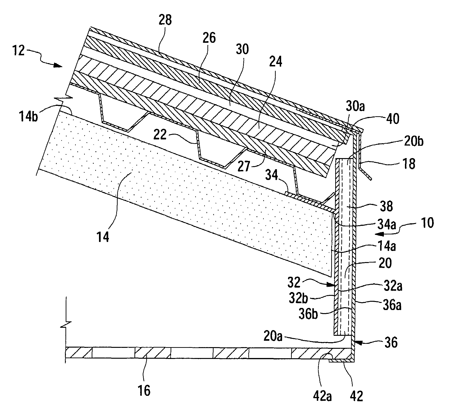
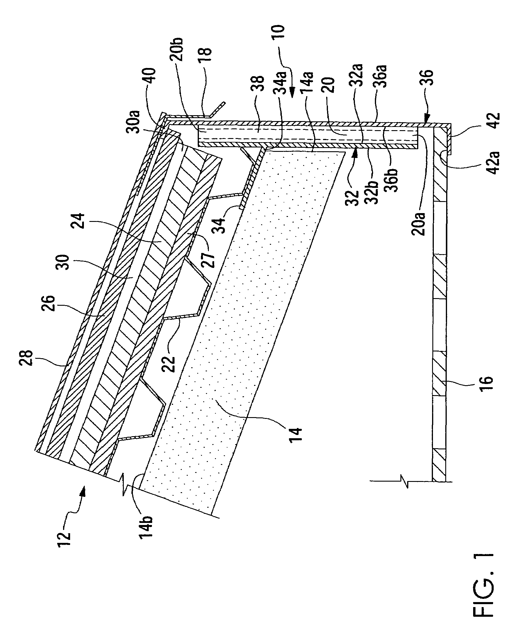
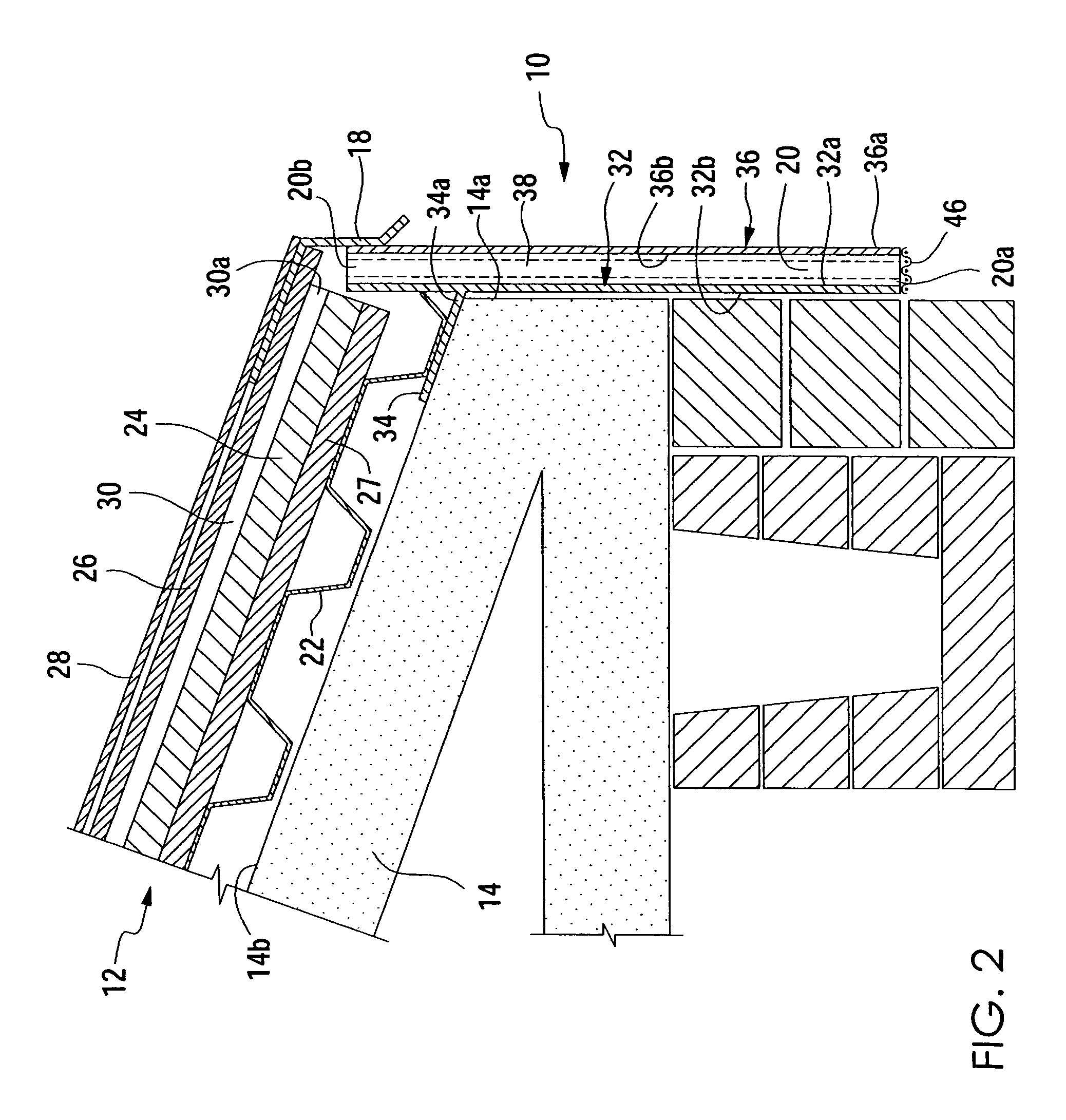
[0022]Referring to the FIGS. 1-5 for a clearer understanding of the invention, it may be seen that the invention contemplates a vented roof system having a structural vent assembly 10 for use along the perimeter of a roof comprising a vented roof deck 12 and a roof deck support structure 14. The structural vent assembly 10 of the present invention is preferably a single, prefabricated assembly ready for field installation during building construction in a one-step procedure. The preferred embodiment of the vent assembly 10 provides an air passage 20 which allows outside air to flow from a vented soffit 16 to a vented roof deck 12 as shown in FIG. 1. Alternatively, the vent assembly 10 of the present invention may be utilized for roof systems not having a soffit panel, such as the roof system shown in FIG. 2. As shown in FIGS. 1 and 2, the vent assembly 10 is shown providing structural support for metal flashing 18; however, the present invention may be utilized to provide structural...


PUM


Abstract

A structural vent assembly comprising a back member having a forward surface and a rear surface; a mount member adapted to be secured to the support structure between the roof deck and the support structure, the mount member having a proximal end fixedly attached to the rear surface; a front member having an outer surface and an inner surface; and means for connecting the forward surface to the inner surface in spaced apart relationship to form a passage for air flow therebetween, the passage having an upper end and a lower end communicating with the air space of the roof deck.

Description

REFERENCE TO RELATED APPLICATIONS[0001]This application claims priority to U.S. patent application Ser. No. 10 / 328,592, filed Dec. 23, 2002, which, in turn, claims priority to U.S. Provisional Application No. 60 / 344,996, filed Jan. 4, 2002.FIELD OF THE INVENTION[0002]The present invention relates to roofing components, and more particularly, to roofing ventilation systems. With even more particularity, the present invention relates to improved vent assemblies for the perimeter of roof systems having vented roof decks.BACKGROUND OF THE INVENTION[0003]Roof systems typically comprise a roof deck system utilized to support a roof membrane such as shingles. The roof deck system of a commercial building is typically comprised of a metal deck such as a sheet of corrugated steel mounted on a roof deck support structure such as steel or wooden roof beams. The metal deck supports insulation that, in turn, supports a wood member such as oriented strand board (“OSB”) or plywood. This wood membe...

Claims


Application Information

Patent Timeline
IPC IPC(8): E04B1/70
CPCE04D13/152
Inventor AYERS, JR., W. HOWARD
Owner AYERS JR W HOWARD
Why Eureka
Try Eureka