Hand-held power tool with a decoupling device

a technology of decoupling device and hand-held power tools, which is applied in the direction of portable power-driven tools, manufacturing tools, drilling machines, etc., can solve the problem of inability to decouple the handle from the rotational oscillation acting on the housing, and achieve the effect of small spring stiffness

Active Publication Date: 2009-11-03
HILTI AG
View PDF15 Cites 26 Cited by
  • Summary
  • Abstract
  • Description
  • Claims
  • Application Information

AI Technical Summary

Benefits of technology

[0011]With a reduced spring stiffness of the first support in the second direction, the decoupling of the handle from the housing vibrations, which are caused by rotational oscillations about the gravity center, in the second direction is effected to a great extent by the spring action at the second spring-mounted support, and the disadvantageous influence of the spring action of the first spring-mounted support the decoupling of the rotational vibrations is prevented to a most possible extent. Thereby, a particularly effective decoupling of the handle from rotational vibrations of the housing is achieved. This indeed insures a particularly comfortable handling of the power tool during an operation.
[0020]It is particularly advantageous when the second elastomeric arrangement has, between the second bar-shaped support member and the second tubular support member, a second support region having circumferentially a smaller radial extension than the region with the star-shaped cross-section. Thereby, at the second spring-mounted support arrangements, with a certain relative displacement of the handle relative to the housing in a radial direction of the second bar-shaped support member, a purposeful progression of the spring stiffness of the second elastomeric arrangement is achieved. The additional increase of the spring characteristic by provision of the second support region can be obtained by forming it with a special shape, e.g., by a predetermined cross-sectional shape, by a variable thickness, or by a predetermined length. In each case, a damaging contact between the handle and the housing can be prevented upon application of a high pressure force or when loosening the jammed working tool also at the second spring-mounted support.

Problems solved by technology

However, the drawback of the known hand-held tool consists in that despite the all-side spring action applied to both spring-mounted means, an adequate decoupling of the handle from rotational oscillations acting on the housing is not possible.

Method used


Image

  • Hand-held power tool with a decoupling device
  • Hand-held power tool with a decoupling device
  • Hand-held power tool with a decoupling device

Examples


Embodiment Construction

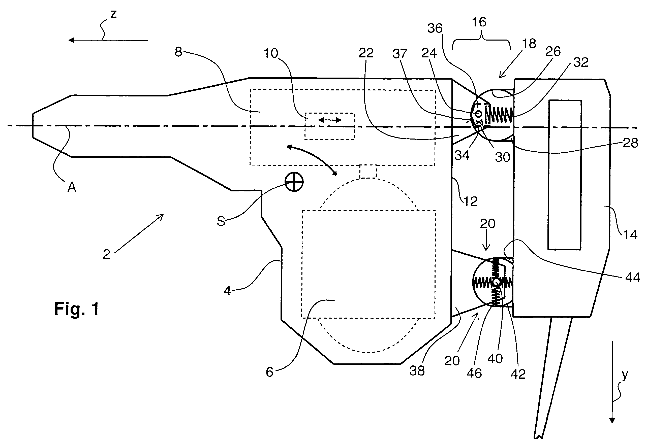
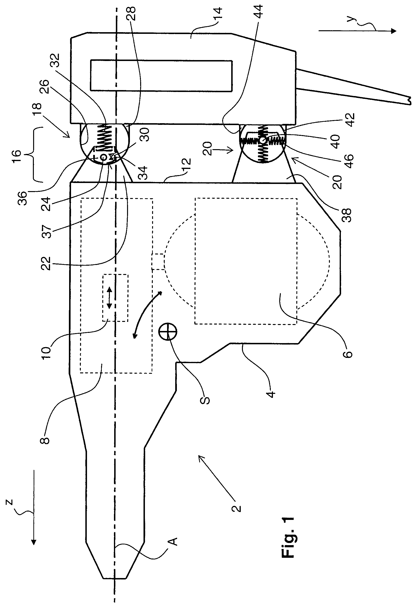
[0031]FIG. 1 shows a principal schematic view of a hand-held power tool 2 according to the present invention and which is formed as an electrical combination hammer that can be alternatively used as a hammer drill or chisel hammer. The power tool 2 has a housing 4 in which a drive motor 6 and an electro-pneumatic drive unit 8, e.g., a percussion mechanism which is driven by the electric motor 6, are located. The drive unit 8 includes a gear unit and operating means 10, e.g., in form of a percussion or impact piston that reciprocates during an operation along an operational axis A which determines a parallel first direction z that corresponds to the operational direction of the hand-held power tool 2. The operational axis A is spaced from the gravity center S of the hand-held power tool 2 which, e.g., can be defined by the gravity center of the mass of the hand-held power tool 2 in a middle position of the operational means 10.

[0032]At the rear side 12 of the housing 4, a handle 14 i...


PUM

PropertyMeasurementUnit
lengthaaaaaaaaaa
spring stiffnessaaaaaaaaaa
gravityaaaaaaaaaa

Abstract

A hand-held power tool includes a spring-mounted decoupling device (16) for supporting a tool handle (14) on the tool housing (4) and having a first spring-mounted support (18) and a second spring-mounted support (20) that is spaced from the operational axis (A) in a second direction (y) perpendicular to the first direction (z) further away than the first spring-mounted support (18) that has a smaller spring stiffness along the second direction (y) than along the first direction (z).

Description

BACKGROUND OF THE INVENTION[0001]1. Field of the Invention[0002]The present invention relates to a hand-held power tool, in particular in form of an electrical combination hammer that can be alternatively used as a hammer drill or a chisel hammer and that includes a housing in which there is provided operational means that reciprocates along an operational axis spaced from the gravity center of the tool and extending parallel to a first direction which corresponds to the operational direction of the tool. E.g., the operational means can be formed as a percussion or impact piston of an electro-pneumatic percussion mechanism. The power tool further includes a handle supported on the housing by a spring-mounted decoupling device for preventing transmission of the housing vibrations to the handle. The decoupling device includes a first spring-mounted support and a second spring-mounted support in form of a pivotal support and that is spaced from the operational axis in a second directio...

Claims


Application Information

Patent Timeline
Patent Type & Authority Patents(United States)
IPC IPC(8): B25F5/02B23B45/16
CPCB25D17/043B25F5/006B25D2211/003B25D2222/57B25D2250/245B25D2250/371B25D2222/69
Inventor FISCHER, AXELMEUER, ROLAND
Owner HILTI AG
Why Eureka
Try Eureka