High efficiency water heater

a high-efficiency, water heater technology, applied in the direction of combustion types, domestic stoves or ranges, combustion using lump and pulverulent fuel, etc., can solve the problems of energy loss, reduce efficiency, and reduce condensation

Inactive Publication Date: 2009-11-10
WOOLLEN DONALD E JR
View PDF17 Cites 19 Cited by
  • Summary
  • Abstract
  • Description
  • Claims
  • Application Information

AI Technical Summary

Problems solved by technology

This type of design requires a tall water heater tank requiring space and not allow for multiple heaters to be stacked.
Any mixing of the hot water with the cold or conduction through the tank walls will increase the temperature of the water at the bottom of the tank and reduce condensation and hence, reduce efficiency.
The described embodiments have improvements in efficiency over prior water heaters, but requires two large-sized water tanks, both having an outer surface exposed to ambient air, a major factor in energy loss.
Additionally, the efficiency of this heater is less than optimal because a percentage of its efficiency is in the form of trapped water vapor that, in this design, is exhausted out the flue as waste along with the other products of combustion.
Additionally, the lower tank cannot be used for hot water storage.

Method used


Image

  • High efficiency water heater
  • High efficiency water heater
  • High efficiency water heater

Examples


Embodiment Construction

[0014]Reference will now be made in detail to the presently preferred embodiments of the invention, examples of which are illustrated in the accompanying drawings. Throughout the following detailed description, the same reference numerals refer to the same elements in all figures.

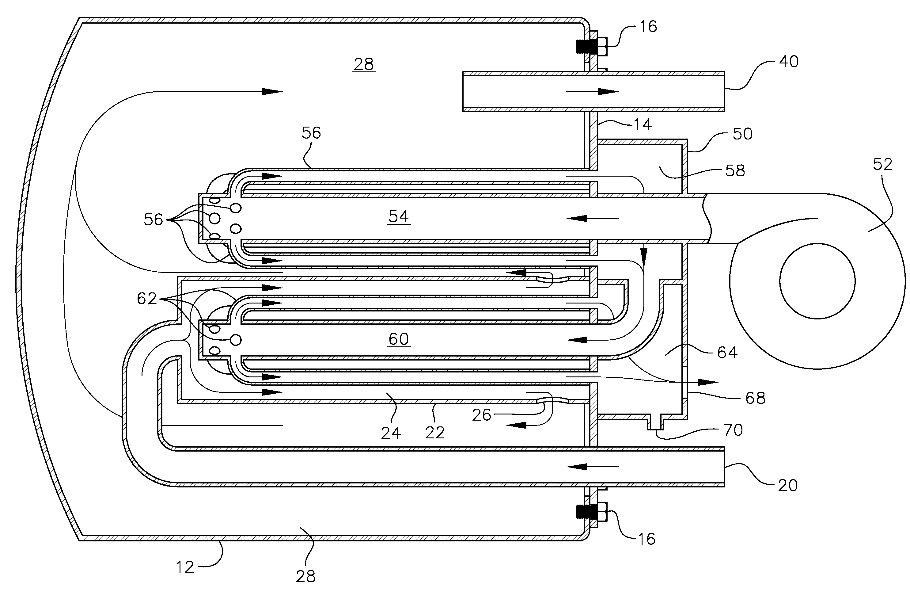
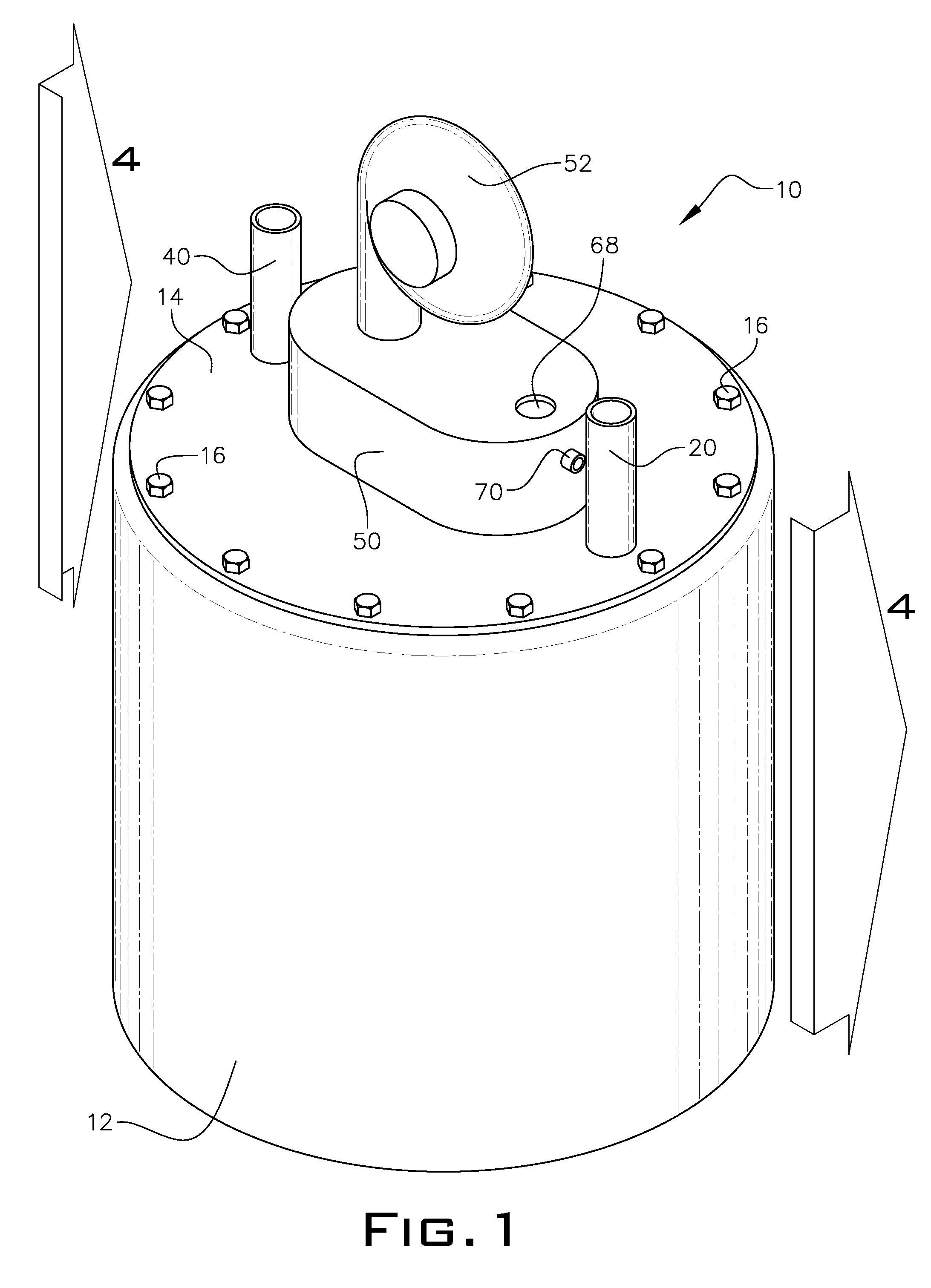
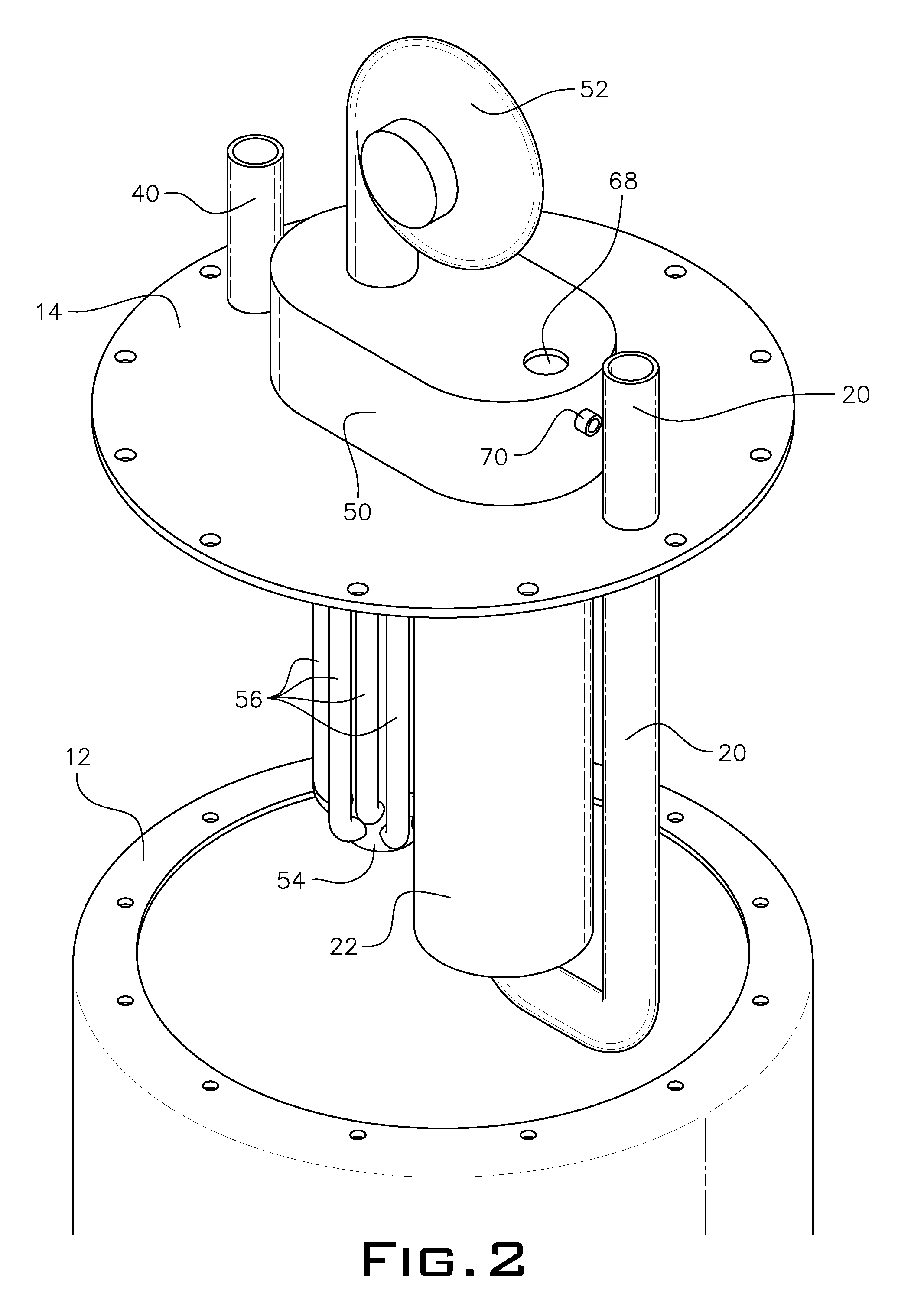
[0015]Referring to FIG. 1, an isometric view of a water heater of a first embodiment of the present invention is shown. The water heater 10 includes an outer tank 12 with a cover plate 14 secured to the outer tank 12 by fasteners 16. In this example, the fasteners are bolts 16 but any type of fastener is acceptable. In some embodiments the cover plate 14 is permanently affixed to the outer tank 12 by adhesive or weld. Apertures in the cover plate 14 are provided to inlet cold water, outlet hot water, input hot gases from the burner 52, outlet intermediate hot gases, inlet intermediate hot gases and outlet exhausts.

[0016]A conventional gas, oil or gas / oil burner 52 is the source of hot gasses. Cold water ent...


PUM


Abstract

An application for a method of heating water includes burning fuel to produce hot gases and heating a first mass of water with a first heat exchanger coupled to the hot gases. Heat remaining after the hot gases pass through the first heat exchanger is used by a second heat exchanger to heat a second mass of water. The first mass of water is partially isolated from the second mass of water and the first mass of water is contained substantially within the second mass of water. The second mass of water is colder than the first mass of water and, thereby, condenses more water vapor out of the hot gases.

Description

FIELD OF THE INVENTION[0001]This invention relates to the field of gas and / or oil fired water heaters and more particularly to an efficient system for utilizing gas and / or oil combustion to heat water.BACKGROUND OF THE INVENTION[0002]Water heaters for commercial and home use are well known in the industry. The most common water heaters have a water tank and a series of heat exchange tubes immersed in the water. Hot gasses from the combustion of gas and / or oil are circulated through the tubes, thereby heating the tubes and transferring heat to the surrounding water. These water heaters utilize what is known thermal stacking—hot water moves toward the top of the tank. In such, the heat exchanger is located toward the bottom of the tank in the coolest water to maximize condensing. This type of design requires a tall water heater tank requiring space and not allow for multiple heaters to be stacked. Any mixing of the hot water with the cold or conduction through the tank walls will incr...

Claims


Application Information

Patent Timeline
Patent Type & Authority Patents(United States)
IPC IPC(8): F24H1/48
CPCF24H1/206F24H1/285F24H1/44F24H9/0021F24H1/26F24H1/36
Inventor ARNOLD, GEORGE R.WOOLLEN, DONALD E.
Owner WOOLLEN DONALD E JR
Why Eureka
Try Eureka