Linear driving device with a self-lubricating assembly

a self-lubricating assembly and driving device technology, applied in the direction of machine/engine, drip or splash lubrication, etc., can solve the problems of insufficient lubrication and energy loss, and achieve the effect of prolonging the lubricating time of the linear driving device, increasing the oil reserve, and being easy to assemble or disassembl

Active Publication Date: 2009-11-10
HIWIN TECH
View PDF21 Cites 15 Cited by
  • Summary
  • Abstract
  • Description
  • Claims
  • Application Information

AI Technical Summary

Benefits of technology

[0008]The primary objective of the present invention is to provide a self-lubricating assembly for a linear driving device that is assembled in a linear driving device and can lubricate the linear driving device automatically when the slide block moves.
[0009]The secondary objective of the present invention is to provide a self-lubricating assembly for a linear driving device, wherein an oil container is supplied with plenty of lubricating oil for prolonging lubricating time of the linear driving device.
[0010]The third objective of the present invention is to provide a self-lubricating assembly for a linear driving device, wherein the oil container is easy to assemble or disassemble since it is detachably disposed on the connecter.
[0012]The self-lubricating assembly for the linear driving device of the present invention is assembled on the slide block of the linear driving device. When the slide block slides on the guideway, the self-lubricating assembly is driven to perform lubricating action. The self-lubricating assembly is provided with an oil container, which is used for storing lubricating oil for increasing the oil reserve in the self-lubricating assembly and prolonging lubricating time of the linear driving device. The oil container is easy to assemble or disassemble since it is detachably disposed on the connecter. In addition, an oil transmitting member is disposed around the inner periphery of the storing tank, so it can absorb the lubricating oil in every corner of the storing tank.

Problems solved by technology

During the course of rotation of the screw or the linear slide of the slide block, it will produce friction, and the friction will change kinetic energy into heat energy, causing energy loss.
Both of the above-mentioned two methods supply oil from the outside, so lubricating oil is likely to drip or to be overly supplied, so it is wasteful, or the lubricating oil is insufficiently supplied and consequently causing insufficient lubrication.

Method used


Image

  • Linear driving device with a self-lubricating assembly
  • Linear driving device with a self-lubricating assembly
  • Linear driving device with a self-lubricating assembly

Examples


Embodiment Construction

[0023]The present invention will be more clear from the following description when viewed together with the accompanying drawings, which show, for purpose of illustrations only, the preferred embodiment in accordance with the present invention.

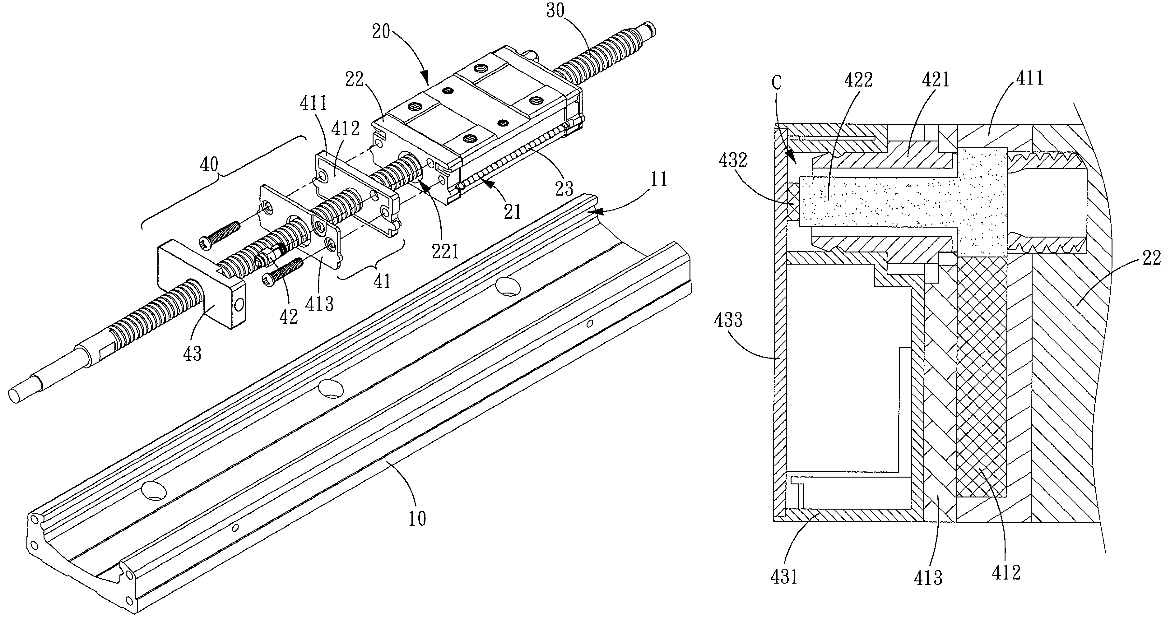
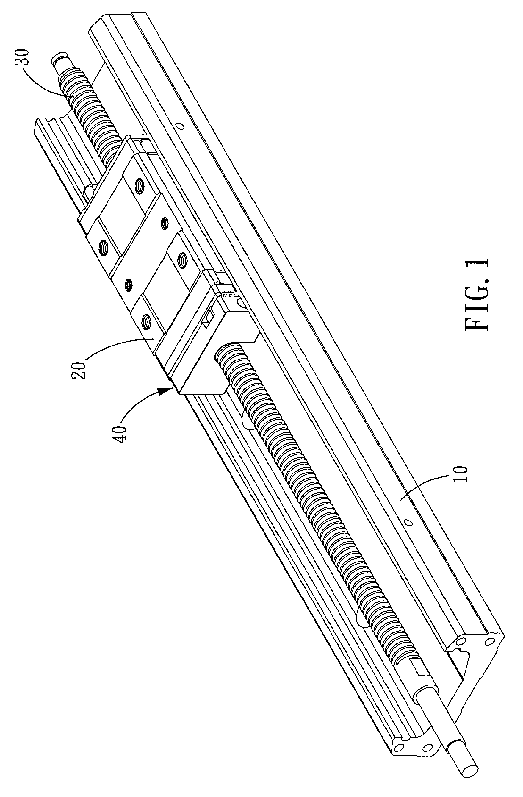
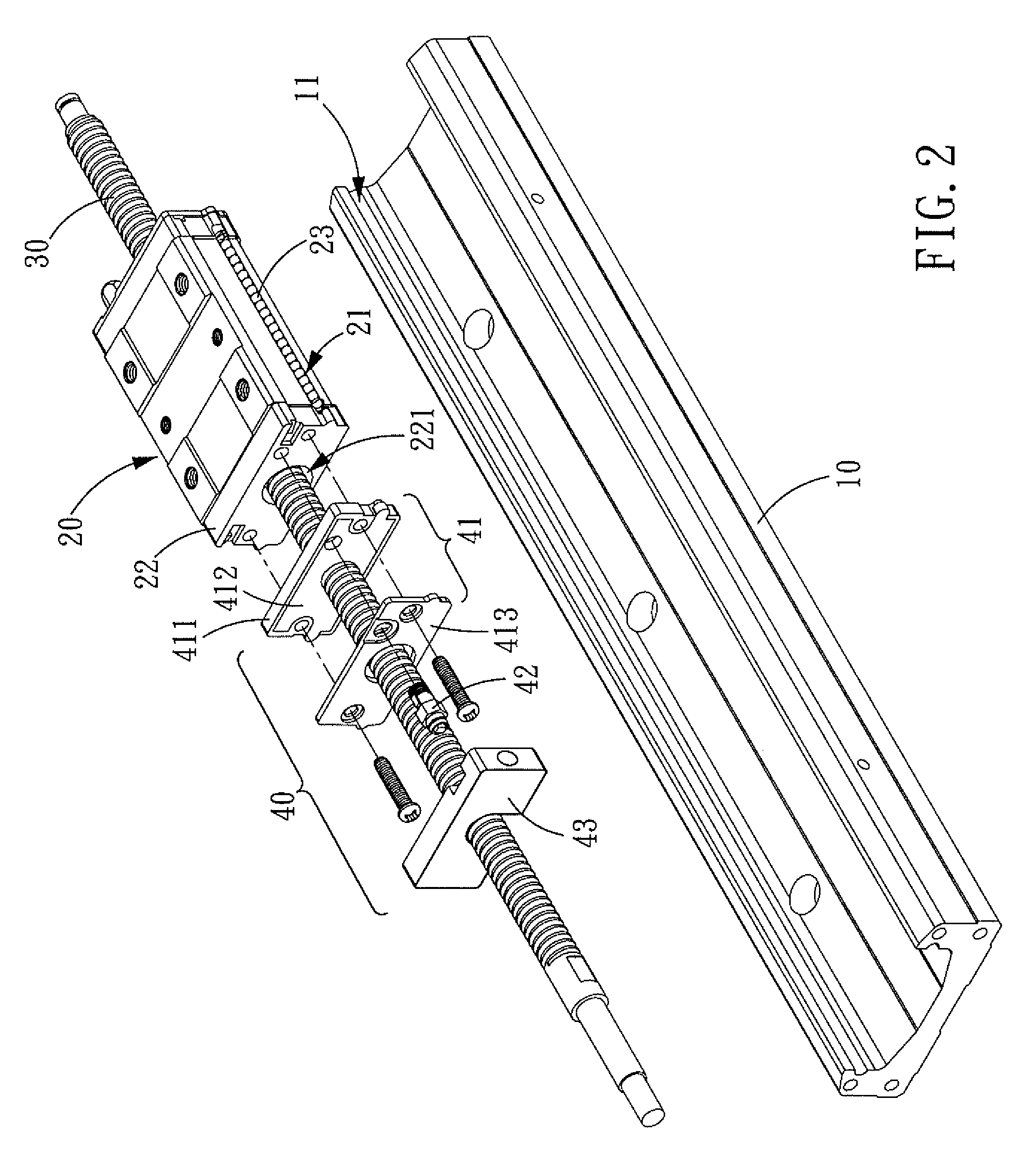
[0024]Referring to FIGS. 1 and 2, a linear driving device with a self-lubricating assembly in accordance with the present invention comprises a guideway 10, a slide block 20, a screw 30 and a self-lubricating assembly 40.

[0025]An elongated guiding groove 11 is defined in the inner surface of either side of the guideway 10 respectively.

[0026]Two grooves 21 are defined at both sides of the slide block 20 and located correspondingly to the elongated guiding grooves 11 of the guideway 10 respectively. A plurality of rolling elements 23 is disposed between each of the two elongated guiding groove 11 of the guideway 10 and the corresponding groove 21 of the slide block 20. The slide block 20 is slideably mounted on the guideway 10 via the rolling el...


PUM


Abstract

A self-lubricating assembly for a linear driving device comprises an oil applying subassembly, an oil transmitting subassembly and an oil container. The oil transmitting subassembly transmits lubricating oil from the oil container to the oil applying subassembly, and the oil applying subassembly is driven by the linear driving device to perform lubricating action automatically. The oil container is provided for storing lubricating oil to prolong lubricating time of the linear driving device.

Description

BACKGROUND OF THE INVENTION[0001]1. Field of the Invention[0002]The present invention relates to a linear driving device, and more particularly to a linear driving device with a self-lubricating assembly.[0003]2. Description of the Prior Art[0004]A conventional linear driving device comprises a guideway, a slide block and a screw. The slide block is slideablely assembled on the guideway. The screw is screwed in the slide block. When the screw rotates, it drives the slide block to slide linearly along the guideway. During the course of rotation of the screw or the linear slide of the slide block, it will produce friction, and the friction will change kinetic energy into heat energy, causing energy loss. Therefore, the linear driving device should be lubricated by lubricating oil for improving energy transmission efficiency.[0005]Conventional methods for lubricating the linear driving device include dispersing lubricating and centralized lubricating. The former refers to a method for ...

Claims


Application Information

Patent Timeline
Patent Type & Authority Patents(United States)
IPC IPC(8): F16H29/04
CPCF16C29/0609F16C33/6659F16C33/664F16C29/063
Inventor LIU, SHIN-TAIHSIEH, MIN-YAO
Owner HIWIN TECH
Why Eureka
Try Eureka