Infinitely-variable transmission with double mode power transmission controlled by a sliding dog for a motor vehicle

a sliding dog and transmission technology, applied in mechanical equipment, transportation and packaging, gearing, etc., can solve the problems of inconvenient operation, inconvenient maintenance, and inconvenient maintenance, so as to simplify the transmission architecture, improve the efficiency of the transmission, and reduce the overall dimensions and production costs.

Inactive Publication Date: 2009-11-10
RENAULT SA
View PDF13 Cites 33 Cited by
  • Summary
  • Abstract
  • Description
  • Claims
  • Application Information

AI Technical Summary

Benefits of technology

[0019]Another object of the present invention is a transmission of this kind in which the efficiency of the transmission is improved.
[0020]Another object of the present invention is a transmission of this kind in which each operating mode is kept stable even if there is a failure of the supply to the means of driving the mode change device.
[0021]Another object of the present invention is to simplify the transmission architecture so as to reduce its overall dimensions and its production cost.
[0022]Another object of the present invention is an infinitely variable transmission with two operating modes in which the switch between the two operating modes is carried out in a particularly simple way.

Problems solved by technology

However, such two-mode transmission architectures, of the known type, have the disadvantage that the mode changes are carried out by multi-disk clutches positioned at the output of the transmission, in such a way that their operation is accompanied by abrupt changes of torque which cause disagreeable sensations for the users.
Another disadvantage of such a transmission, described for example in U.S. Pat. No. 5,558,589 and U.S. Pat. No. 5,935,035, consists in the complexity of the architecture, due in particular to the presence of at least two clutches and one brake.
This requires a relatively complex hydraulic circuit to provide a suitable supply to the two hydraulic brakes whose bulkiness is an additional drawback.
Moreover, the energy consumption required for actuating the linings of the brakes used and for keeping them in the locked position causes a decrease in the efficiency of the transmission.

Method used


Image

  • Infinitely-variable transmission with double mode power transmission controlled by a sliding dog for a motor vehicle
  • Infinitely-variable transmission with double mode power transmission controlled by a sliding dog for a motor vehicle
  • Infinitely-variable transmission with double mode power transmission controlled by a sliding dog for a motor vehicle

Examples


Embodiment Construction

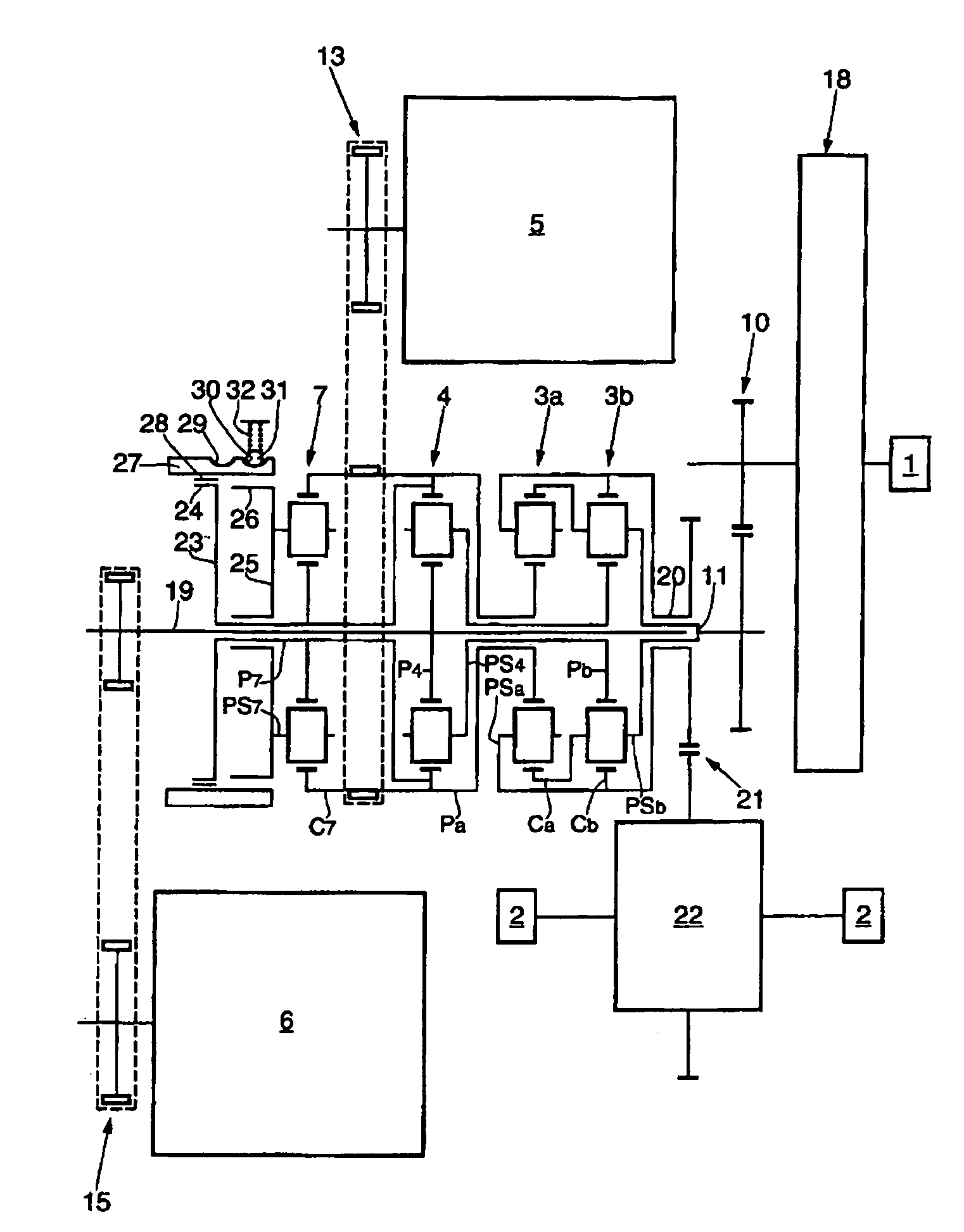
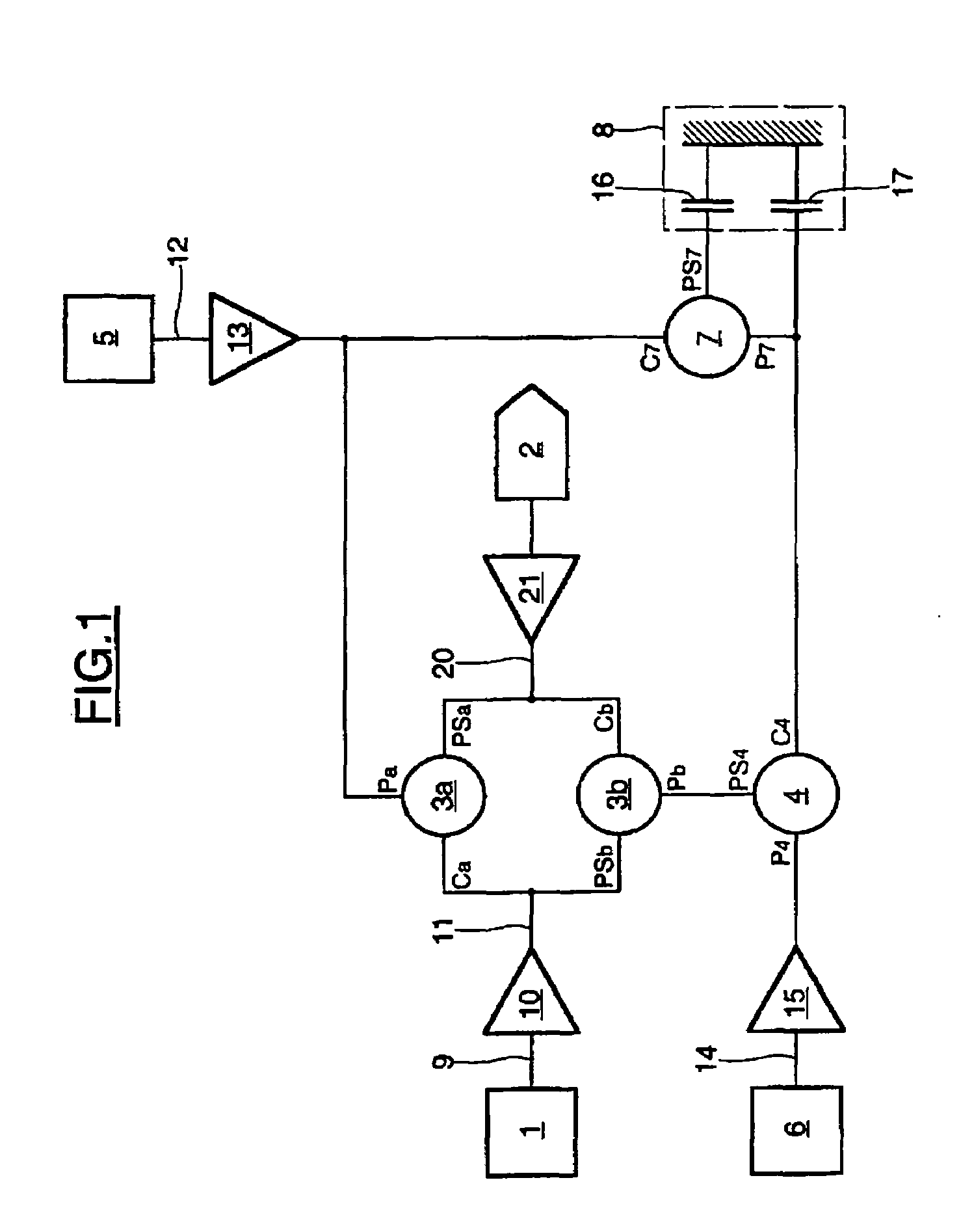
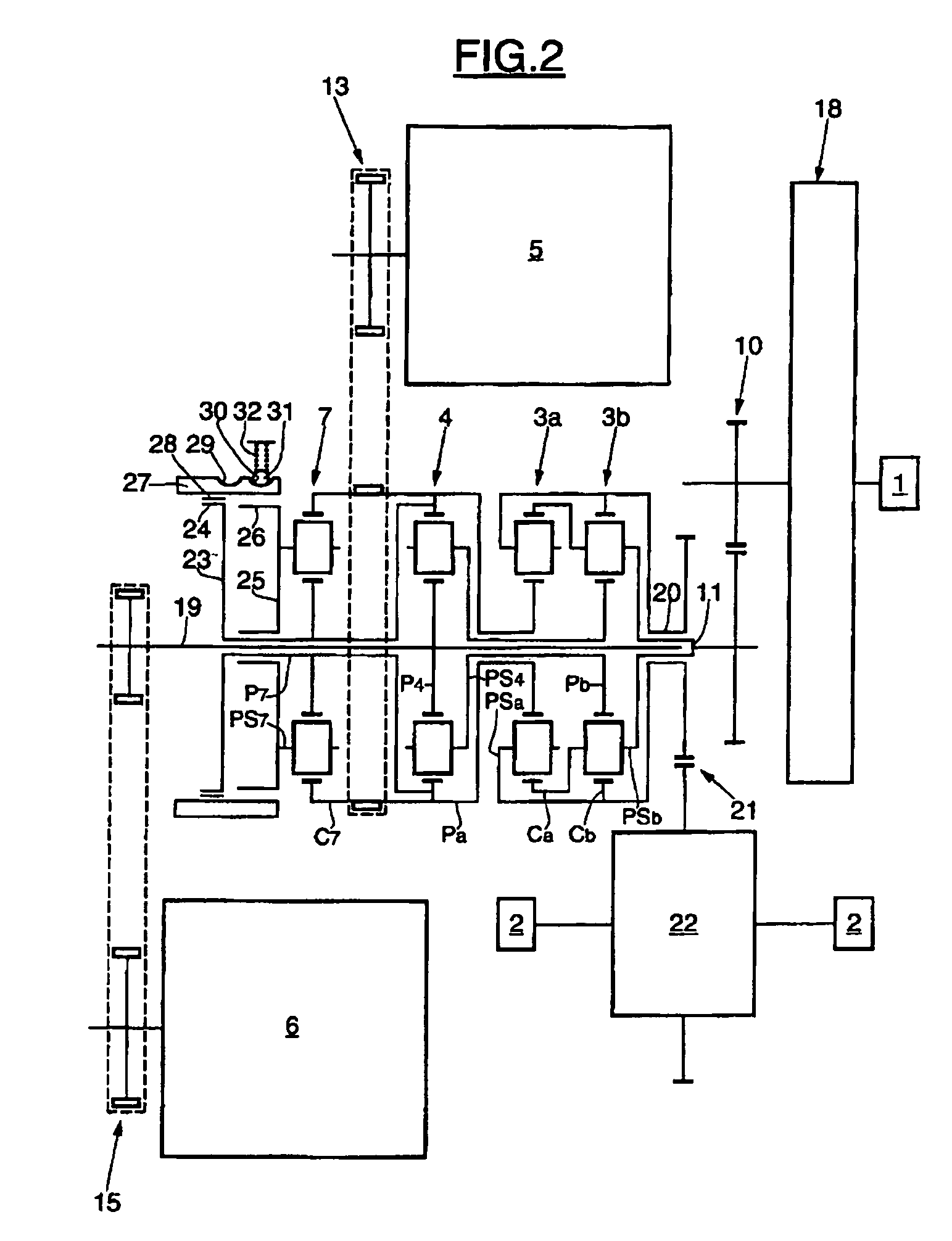
[0039]As shown in the functional diagram of FIG. 1, the infinitely variable transmission is fitted between a combustion engine 1 which constitutes a power unit of a motor vehicle and the axle 2 of the driving wheels of the vehicle which constitutes the driven element. The transmission comprises a first main power branching path with a compound epicyclic gear train 3a, 3b. The ring gear Ca of the gear train 3a is fixed to the planet carrier PSb of the gear train 3b. Similarly, the ring gear Cb of the gear train 3b is fixed to the planet carrier PSa of the gear train 3a.

[0040]A second power branching path comprises a first simple epicyclic gear train indicated by 4. Two electrical machines, indicated by 5 and 6 respectively, constitute a continuous speed controller. Finally, a second simple epicyclic gear train indicated by 7, acting as a mode changing device, is associated with an engagement / disengagement unit 8 and completes the essential structure of the transmission.

[0041]The pow...


PUM


Abstract

An infinitely-variable transmission with double mode power transmission for a motor vehicle, provided with a combustion engine, including a first power transmission path with a composite epicyclic gear train connecting the combustion engine to the vehicle wheels, a second power transmission path with a simple epicyclic gear train, two electric motors providing a continuous speed variator, a second simple epicyclic gear train for mode change, and an engagement/disengagement unit that can block or release a mode-changing body in the second epicyclic gear train, according to the operating mode. The engagement/disengagement body includes a sliding sleeve with a dog tooth, which can be displaced by a hydraulic actuator and with two sets of dog teeth fixed to a mode-changing body in the second epicyclic gear train.

Description

BACKGROUND OF THE INVENTION[0001]The present invention relates to an infinitely variable transmission with two-mode power branching, for a motor vehicle equipped with a combustion engine.FIELD OF THE INVENTION[0002]With this kind of power branching transmission it is possible to obtain continuous variation from a reverse ratio to a forward ratio, passing through a special position called the “neutral engaged” position, in which the speed of the vehicle is zero, at any speed of the combustion engine.DESCRIPTION OF RELATED ART[0003]Power branching transmissions are of several types.[0004]In a first type known as “input coupled”, the transmission includes a pair of power branching pinions which take power from the input of the mechanism and a “combining” epicyclic gear train which combines the powers at the output of the mechanism. The transmission also includes a speed controller.[0005]In another type, called “output coupled”, the transmission includes a power-dividing epicyclic gear ...

Claims


Application Information

Patent Timeline
Patent Type & Authority Patents(United States)
IPC IPC(8): F16H3/72F16H3/44B60K6/365B60K6/387B60K6/445F16H59/08F16H63/30
CPCB60K6/365B60K6/387B60K6/445F16H3/728F16H63/3023Y02T10/6239F16H2037/102F16H2037/104F16H2037/106F16H2200/2012Y02T10/62F16H63/30
Inventor PARTHUISOT, JEAN-PIERRECASENAZ, ROBERT
Owner RENAULT SA
Why Eureka
Try Eureka