
Surface acoustic wave motor

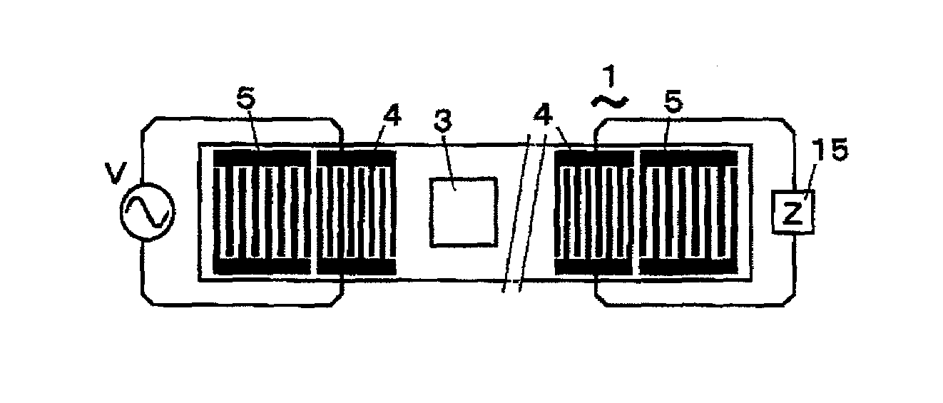
a surface acoustic wave and motor technology, applied in piezoelectric/electrostrictive/magnetostrictive devices, piezoelectric/electrostriction/magnetostriction machines, electrical apparatus, etc., can solve the problem of low energy supply efficiency and the limitation of the power reduction of the conventional surface acoustic wave motor to drive the slider b>3, and achieve the effect of efficient energy recovery

Inactive Publication Date: 2009-11-10
MATSUSHITA ELECTRIC WORKS LTD +1
View PDF11 Cites 6 Cited by
  • Summary
  • Abstract
  • Description
  • Claims
  • Application Information

AI Technical Summary

Benefits of technology

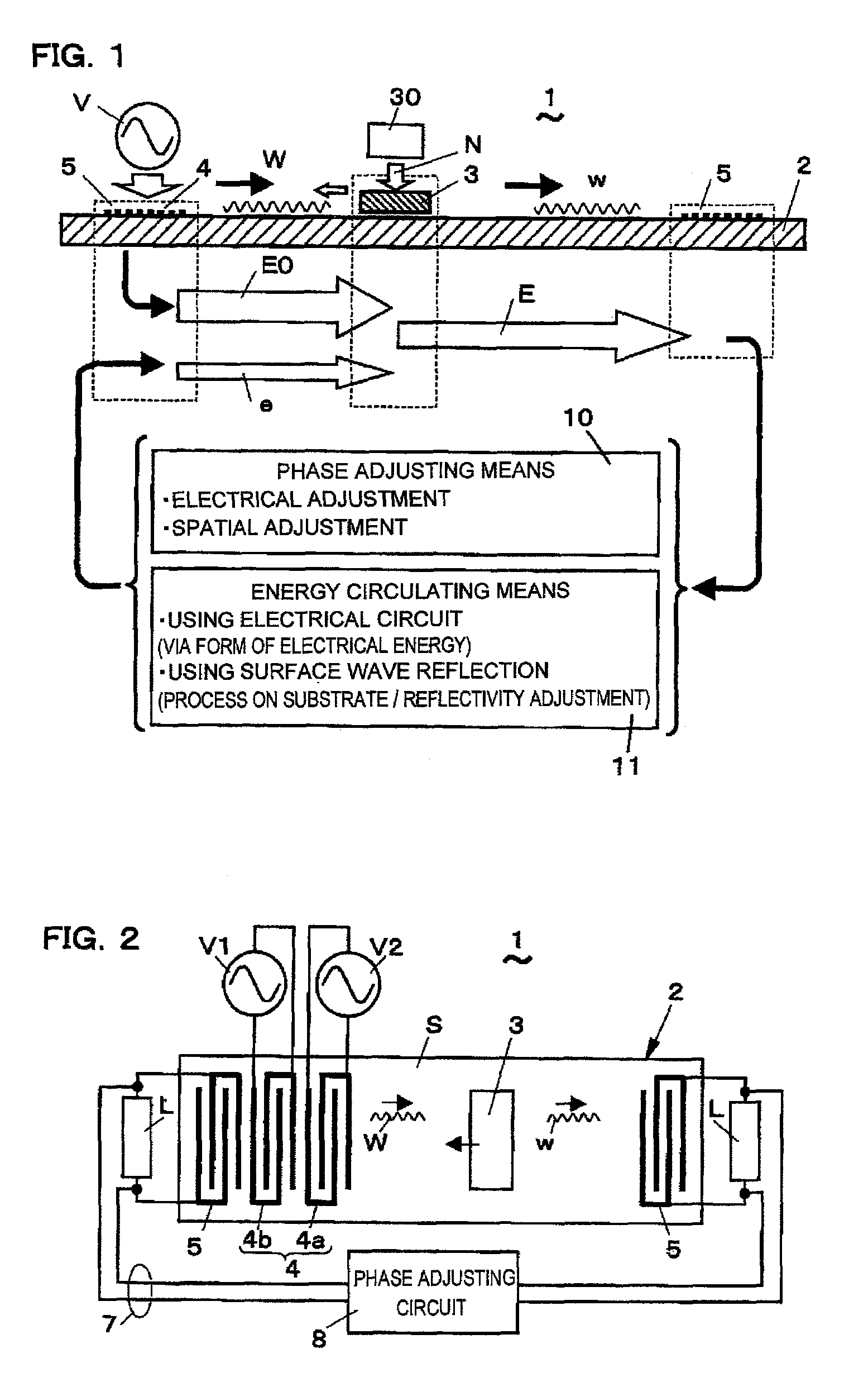
[0019]When the phase adjustment is made before the recovery, the energy of the surface acoustic wave can be efficiently recovered. Further, when the adjustments are made after the recovery and at the supply stage, it is possible to generate a driving surface acoustic wave with a high energy efficiency, i.e. a driving surface acoustic wave effectively used for the slider. Thus, the energy recovery type surface acoustic wave motor of the present invention can adjust a phase change at the time of energy recovery and supply by using the phase adjusting means so as to align the phase of the surface acoustic wave. Accordingly, it is possible to avoid interference between surface acoustic waves of different phases which makes the energy ineffective, achieving an increase in the energy efficiency.
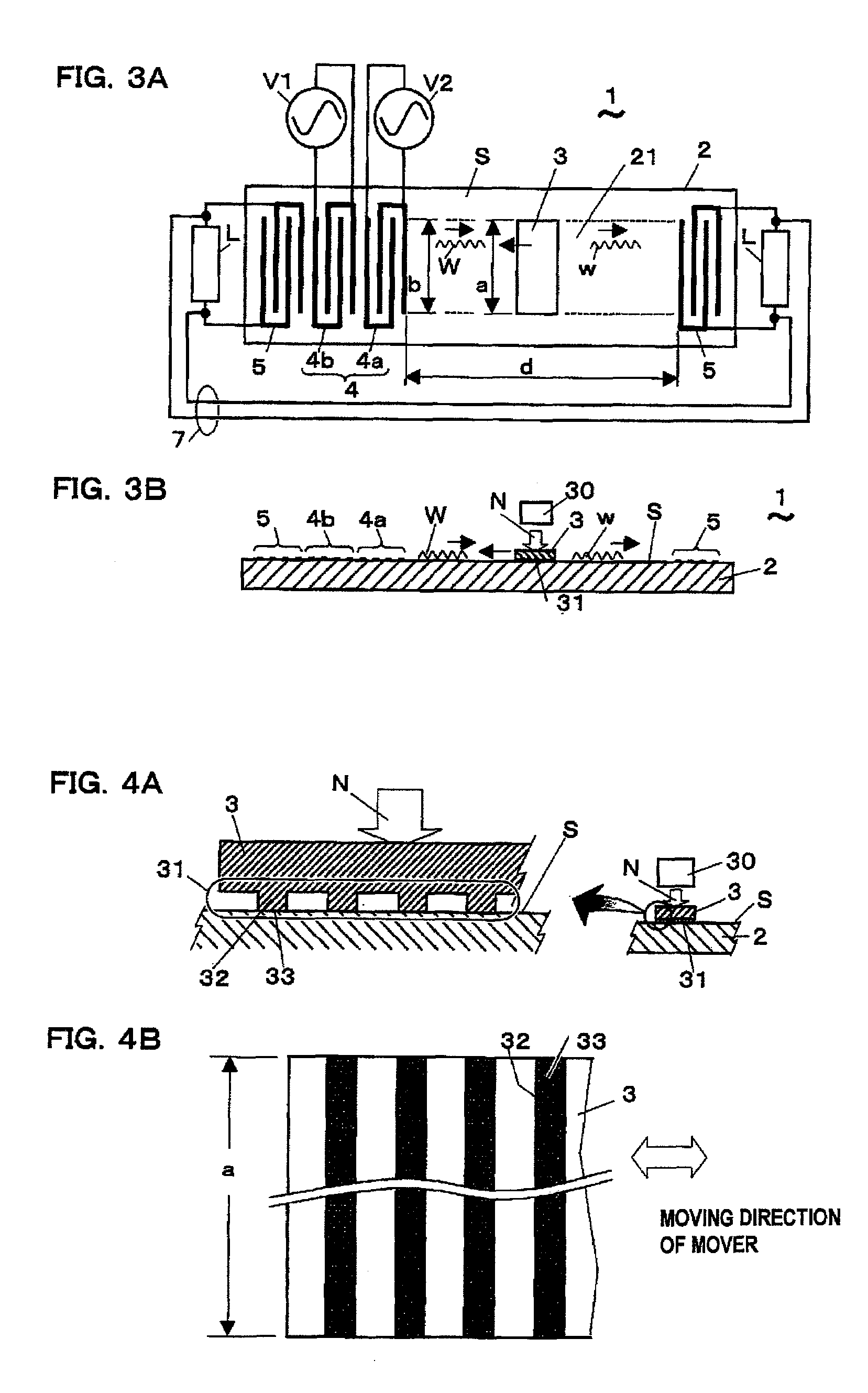
[0053]This arrangement allows the contact portion of the slider with the surface of the surface acoustic wave substrate to be uniform over the entire width thereof in a width direction perpendicular to the direction of travel of the surface acoustic wave. Thus, phase changes occurring in the width direction of the slider are substantially the same, making it possible to allow the surface acoustic wave to arrive at the recovery interdigital electrode with a uniform phase, and thereby efficiently recover the energy.

Problems solved by technology

However, the energy recovery type surface acoustic wave motors disclosed in the above-mentioned FIGS. 25A and 25B and Japanese Laid-open Patent Publication Hei 11-146665 have problems as described below.
However, if not in phase, the energy Eβ is lower than the energy E1(Eα1) (sic, correctly: Eβ1), causing a lower energy supply efficiency.
Thus, a conventional surface acoustic wave motor still has a limitation in the reduction in the power to drive the slider 3.

Method used


Image

  • Surface acoustic wave motor
  • Surface acoustic wave motor
  • Surface acoustic wave motor

Examples


first embodiment

[0100]FIG. 2 shows a surface acoustic wave motor 1 of a first embodiment. The surface acoustic wave motor 1 comprises: a surface acoustic wave substrate 2; recovery interdigital electrodes 5 placed on its surface S forward and backward in the direction of travel of a surface acoustic wave (rightward and leftward in the drawing) to make an electromechanical conversion between electrical energy and mechanical energy for recovering and supplying energy; a driving interdigital electrode 4 placed between the two recovery interdigital electrodes 5 and connected to external power supplies V1 and V2 for complementing energy; a slider 3 placed to contact the surface S of the surface acoustic wave substrate 2 while being provided with an applied pressure N by pressure applying means 30; wiring 7 for connecting the two recovery interdigital electrodes 5; and a phase adjusting circuit 8 inserted in the wiring 7.

[0101]The surface acoustic wave substrate 2 and the slider 3 in the surface acoustic...

second embodiment

[0108]FIGS. 3A and 3B show a surface acoustic wave motor 1 of a second embodiment, while FIGS. 4A and 4B show a structure of a contact portion of a slider 3 with a surface acoustic wave substrate 2 in the surface acoustic wave motor 1. Differently from the above-mentioned surface acoustic wave motor 1 of the first embodiment, this surface acoustic wave motor 1 does not have a phase adjusting circuit 8. The phase adjustment in this surface acoustic wave motor 1 is made by an adjustment of the width of the slider 3 and the widths of the respective interdigital electrodes, and by an adjustment of the length of a region in which the surface acoustic waves W and w are present. In other words, the phase adjusting means 10 in this surface acoustic wave motor 1 uses a spatial adjustment process to make a phase adjustment before energy recovery. Except for these points, the surface acoustic wave motor 1 of the second embodiment is similar to the above-mentioned surface acoustic wave motor 1 ...

third embodiment

[0117]FIGS. 5A to 5C show a surface acoustic wave motor 1 of a third embodiment, while FIGS. 6A to 6C show reflectivity characteristics of interdigital electrodes. The surface acoustic wave motor 1 of the present embodiment circulates recovered energy in the form of mechanical energy to the supply side. This is the point in which it is different from the surface acoustic wave motors 1 of the above-mentioned first and second embodiments. More specifically, the recovery and circulation of energy are performed by a surface acoustic wave traveling reversely on a surface S of a surface acoustic wave substrate 2, namely as a reflected wave, in the form of mechanical energy, not in the form of electrical energy. The energy circulating means 11 in the present embodiment is the surface S of the surface acoustic wave substrate 2.

[0118]The surface acoustic wave motor 1 of the present embodiment comprises: the surface acoustic wave substrate 2; a pair of interdigital electrodes 4 placed opposit...


PUM


Abstract

In an energy recovery type surface acoustic wave motor, an increase in energy efficiency at the time of energy recovery and supply is achieved by adjusting phase change. A surface acoustic wave motor comprises: a surface acoustic wave substrate; a slider provided with an applied pressure; a driving interdigital electrode connected to an external power supply for generating a driving surface acoustic wave on a surface so as to drive the slider by a frictional force which is generated on a contact surface of the slider with the surface acoustic wave substrate based on the surface acoustic wave and the applied pressure; recovery interdigital electrodes placed forward and backward in the direction of travel of the surface acoustic wave for recovering energy of a surface acoustic wave unused to drive the slider, and for using that energy to generate a surface acoustic wave; and phase adjusting means for matching the phase of a surface acoustic wave generated by the recovery interdigital electrodes to the phase of the driving surface acoustic wave generated by the driving interdigital electrode.

Description

TECHNICAL FIELD[0001]The present invention relates to a surface acoustic wave motor, and more particularly to an energy recovery type surface acoustic wave motor.BACKGROUND ART[0002]In the prior art, ultrasonic motors are known as actuators. One of the ultrasonic motors is a motor using surface acoustic wave (SAW), namely a surface acoustic wave motor. The surface acoustic wave is, for example, a wave of oscillation (Rayleigh wave) which is based on an elliptic motion generated in the surface of an elastic body, and which propagates on the surface of the elastic body. The driving force of the motor is a frictional force which is output based on this elliptic motion. The surface acoustic wave motor is expected for use as a small size motor having excellent operational characteristics of high speed, high response and high thrust. For example, a moving speed of 1 m / sec has been achieved as its characteristics. Further, a demonstration has been made that it can produce a thrust equal to...

Claims


Application Information

Patent Timeline
Patent Type & Authority Patents(United States)
IPC IPC(8): H03H9/25
CPCH02N2/08
Inventor KIRIGAYA, MASAHIROSATO, MASAHIROISHIGAMI, YOUHEISAWADA, KAZUOKUROSAWA, MINORU
Owner MATSUSHITA ELECTRIC WORKS LTD
Learn More