
High efficiency resonant ballast

a resonant ballast, high-efficiency technology, applied in the direction of instruments, basic electric elements, light sources, etc., can solve the problems of high switching loss on switches b>10/b> and b>15

Inactive Publication Date: 2009-11-10
FAIRCHILD TAIWAN
View PDF2 Cites 0 Cited by
  • Summary
  • Abstract
  • Description
  • Claims
  • Application Information

AI Technical Summary

Benefits of technology

The solution enables automatic soft switching, reducing switching losses and enhancing efficiency while maintaining a low-cost design, effectively addressing the inefficiencies of conventional ballast circuits.

Problems solved by technology

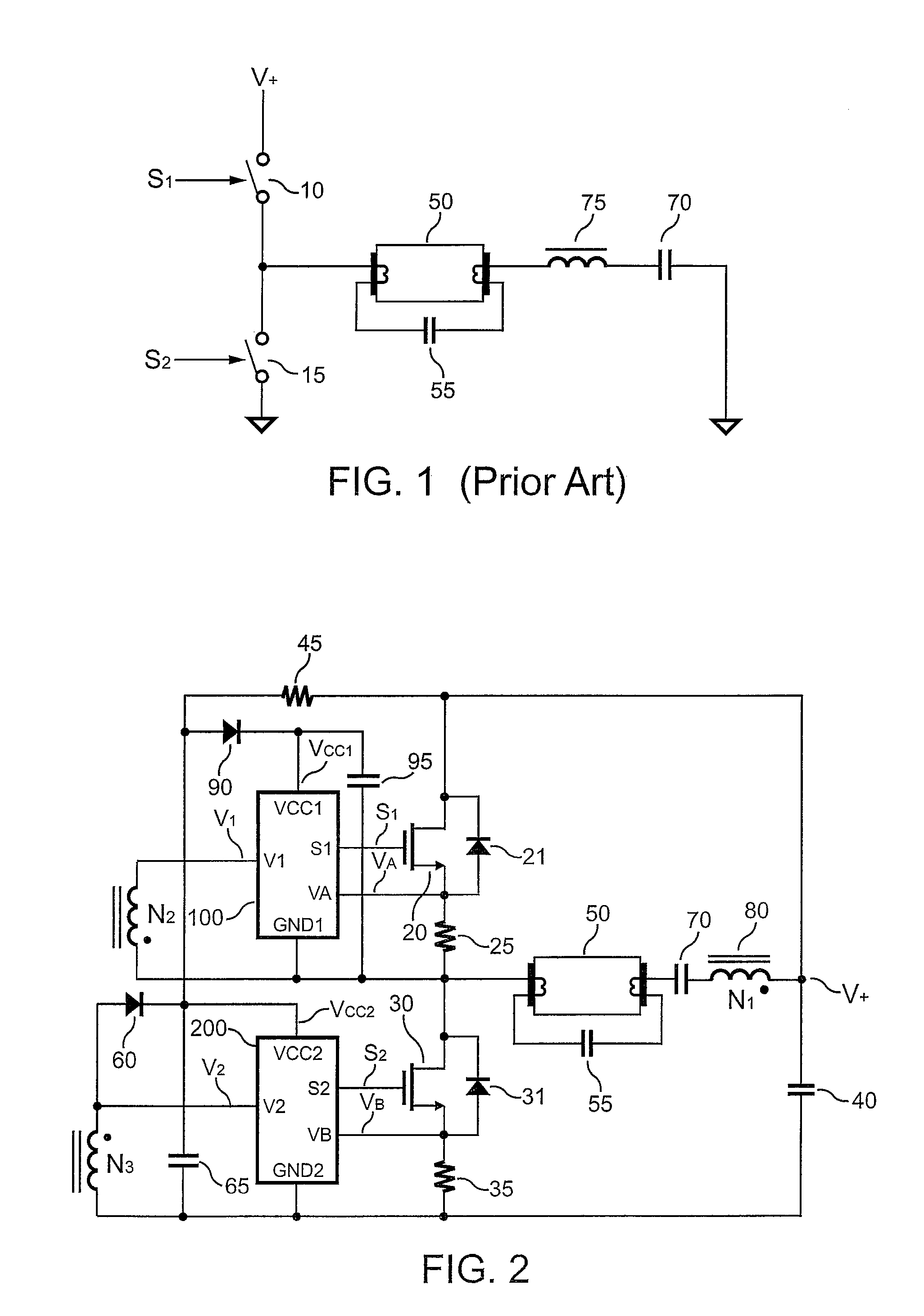
Therefore, in recent development, issues such as efficiency improvement and power saving for a ballast of the fluorescent lamp are deeply concerned. FIG. 1 shows a conventional electronic ballast circuit having a resonant circuit.
The drawback of this circuit is high switching loss on switches 10 and 15.

Method used


Image

  • High efficiency resonant ballast
  • High efficiency resonant ballast
  • High efficiency resonant ballast

Examples


Embodiment Construction

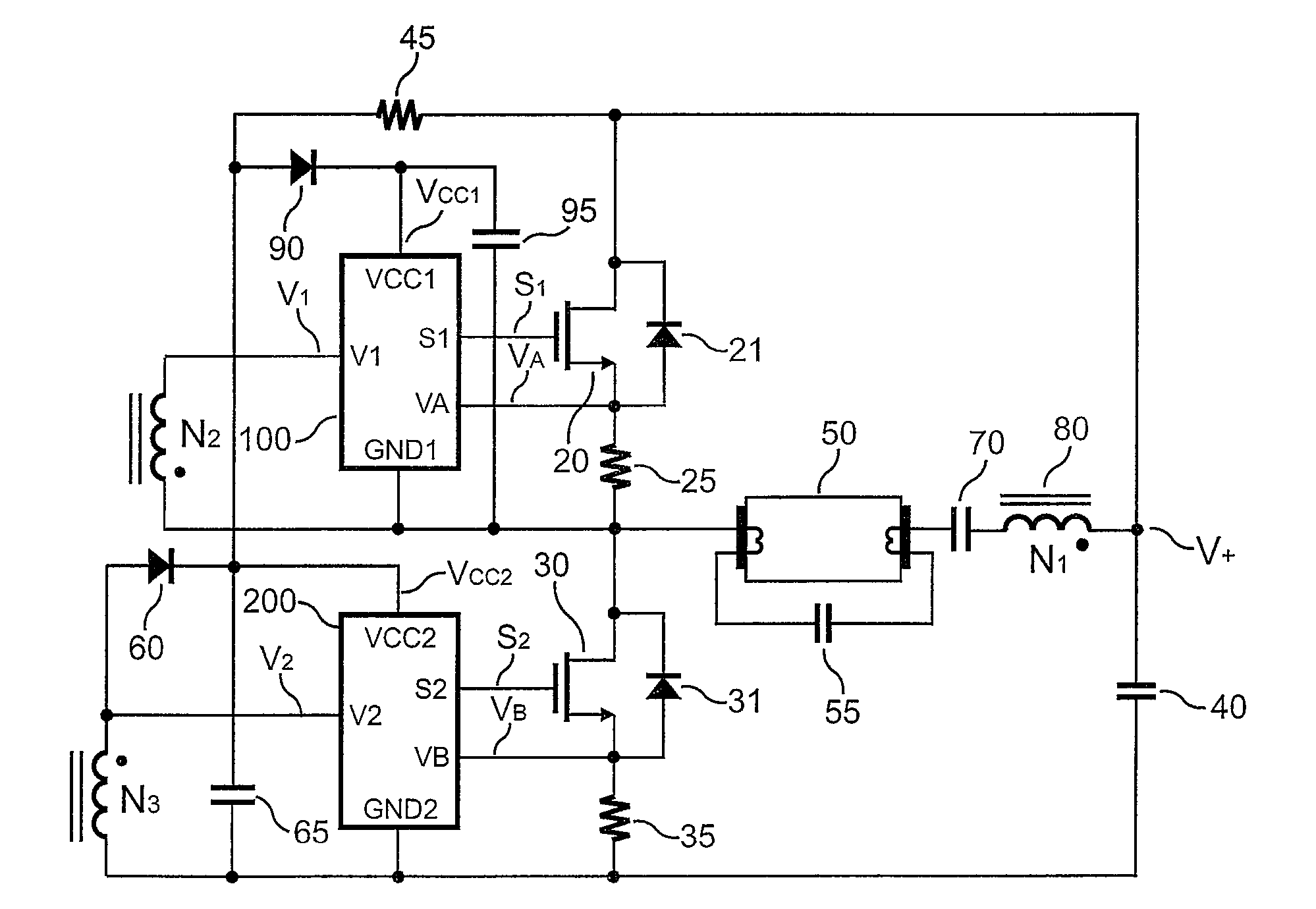
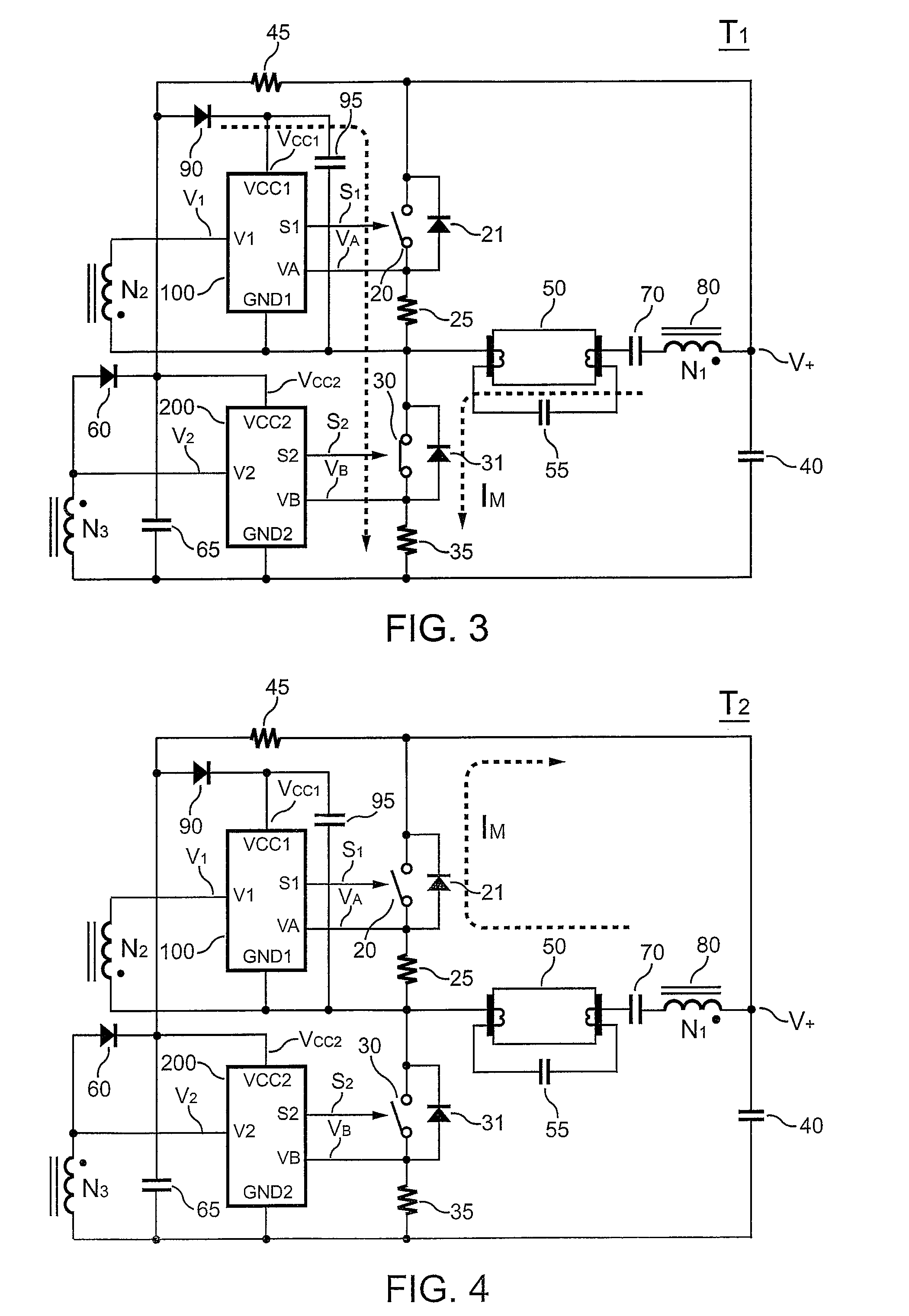
[0019]FIG. 2 shows a ballast circuit according to an embodiment of the present invention. A capacitor 70 and a transformer 80 are connected in series to form a resonant circuit for operating a fluorescent lamp 50. The resonant circuit produces a sine-wave current to drive the fluorescent lamp 50. A first transistor 20 is coupled to switch the resonant circuit. A first resistor 25 is connected in series with the first transistor 20 to detect a switching current for generating a first current signal VA. The first transistor 20 is controlled by a first switching signal S1. A second transistor 30 is coupled to the resonant circuit to supply an input voltage V+ to the resonant circuit. A second resistor 35 is connected in series with the second transistor 30 to detect the switching current for generating a second current signal VB. The second transistor 30 is controlled by a second switching signal S2. A first winding N1 of the transformer 80 is connected in series with the fluorescent l...


PUM


Abstract

The present invention provides a low-cost ballast circuit for fluorescent lamps. A resonant circuit has a transformer to operate the fluorescent lamp. The fluorescent lamp is connected in series with a first winding of the transformer. A first transistor and a second transistor are coupled to switch the resonant circuit. A second winding and a third winding of the transformer are used for generating control signals in response to a switching current of the resonant circuit. Furthermore, the present invention achieves soft operation for the first transistor and the second transistor.

Description

BACKGROUND OF THE INVENTION[0001]1. Field of the Invention[0002]The present invention generally relates to a switching circuit, and more particularly, to a ballast switching circuit.[0003]2. Description of Related Art[0004]Fluorescent lamps are the most popular light sources in our daily lives. To improve the efficiency of fluorescent lamps significantly saves energy. Therefore, in recent development, issues such as efficiency improvement and power saving for a ballast of the fluorescent lamp are deeply concerned. FIG. 1 shows a conventional electronic ballast circuit having a resonant circuit. A half-bridge inverter consists of two switches 10 and 15, which are complementarily switched on / off with 50% duty cycle at a desired switching frequency. The resonant circuit is composed of an inductor 75, a capacitor 70 to operate a fluorescent lamp 50. A capacitor 55 connected in parallel with the fluorescent lamp 50 operates as a start-up circuit. Once the fluorescent lamp 50 starts up, t...

Claims


Application Information

Patent Timeline
Patent Type & Authority Patents(United States)
IPC IPC(8): H05B37/02
CPCH05B41/2825H05B41/2856H05B41/2828Y10S315/05
Inventor YANG, TA-YUNG
Owner FAIRCHILD TAIWAN
Learn More