Supercharge Your Innovation With Domain-Expert AI Agents!

Magnetic line-type position-angle detecting device

a position-angle detection and magnetic line technology, applied in the direction of measuring devices, magnetic measurements, instruments, etc., can solve problems such as adjustment, and achieve the effect of simple structure and compact structur

Inactive Publication Date: 2009-11-10
NTN CORP
View PDF8 Cites 9 Cited by
  • Summary
  • Abstract
  • Description
  • Claims
  • Application Information

AI Technical Summary

Benefits of technology

The present invention provides a magnetic line-type position-angle detecting device with high resolution and inexpensive construction. The device includes a magnetic line sensor with multiple magnetic sensor elements arranged in a linear array, a magnetic generating element held in face-to-face relation to the sensor, and a scanning circuit for sequentially selecting one of the sensor elements and amplifying its detection signal. The device can detect the position of the magnetic generating element with high precision without being affected by external magnetic fields. The position of the magnetic generating element can be calculated by detecting two zero-crossing positions in the distribution of the magnetic fields and calculating the intermediate point between them. This allows for the accurate detection of the position of the magnetic generating element moving linearly.

Problems solved by technology

The position sensors of the optical, electrostatic capacitance detecting and magnetic types referred to above involves various problems in that they are expensive, require adjustments and are capable of only detecting a relative displacement.

Method used


Image

  • Magnetic line-type position-angle detecting device
  • Magnetic line-type position-angle detecting device
  • Magnetic line-type position-angle detecting device

Examples


first embodiment

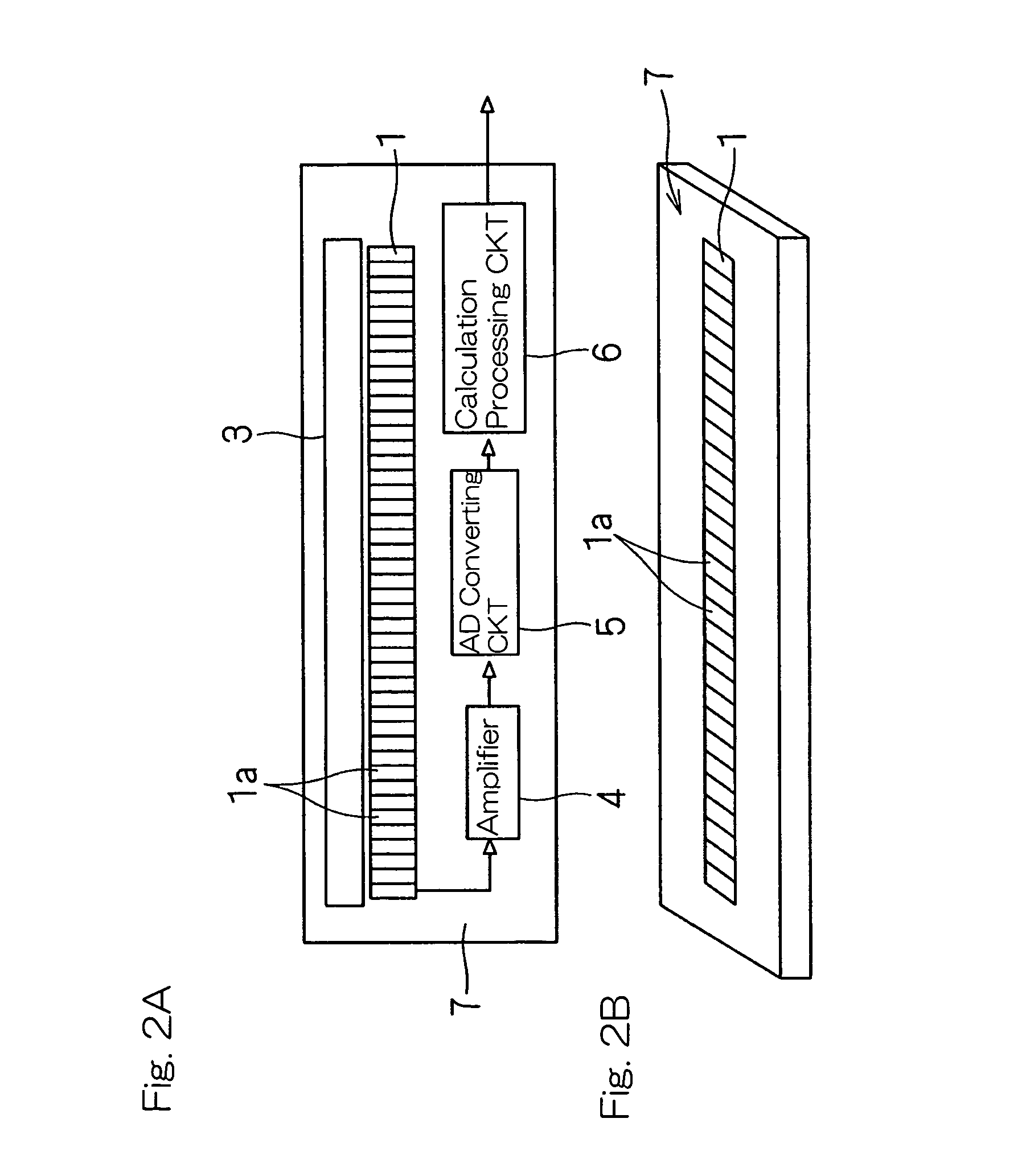
[0042]A first preferred embodiment of the present invention will be described in detail with particular reference to FIGS. 1 to 5. FIG. 1 illustrates a basic structure of a magnetic line-type position-angle detecting device according to this This magnetic line-type position-angle detecting device includes a sensor chip 7 having a magnetic line sensor 1 (FIG. 2B), and a magnetic generating element 2 held in face-to-face relation with the magnetic line sensor 1 spacedly on a non-contact basis and movable in a direction X, in which sensor elements of the magnetic line sensor 1 are arrayed. The sensor chip 7 is fixed to a stationary side member 11 whereas the magnetic generating element 2 is fixed to a movable side member 12 capable of linearly moving in parallel to the longitudinal direction of the sensor chip 7.

[0043]The magnetic line sensor 1 is a sensor operable to detect magnetism of the magnetic generating element 2 and is made up of a plurality of sensor elements 1a arrayed in l...

fourth embodiment

[0079]Advantages of the fourth embodiment described above are summarized as follows:

[0080](1) Detection of the angle with high resolution can be accomplished with a simplified structure.

[0081](2) Since the magnetic line sensor 1 and the processing circuit can be integrated together, the detecting device can have a compact structure.

[0082](3) Since the component parts are integrated on the silicon chip, it is inexpensive.

[0083](4) The resolution can be increased with increase of the distance of arrangement from the rotation axis.

[0084](5) Because of the system of detecting the zero-crossing position, the position detection can be accomplished without being affected by a change in the gap distance of arrangement between the magnetic generating element 2 and the sensor 1.

[0085]A fifth preferred embodiment of the present invention is shown in FIG. 15. The magnetic line-type position-angle detecting device according to this fifth embodiment is similar to the previously described fourth e...


PUM


Abstract

To provide a magnetic line-type position-angle detecting device capable of detecting an absolute position on a non-contact basis and with high resolution and inexpensive construction, the magnetic line-type position-angle detecting device includes a magnetic line sensor 1 having a plurality of magnetic sensor elements 1a arranged in line, and a magnetic generating element 2 confronting the magnetic line sensor and movable in a direction conforming to the line of the magnetic sensor elements 1a. The magnetic sensor elements 1a of the magnetic line sensor 1 are sequentially selected by a scanning circuit 3, a signal from the selected sensor element 1a is processed into a digital signal through an amplifier 4, and an analog-to-digital converting circuit 5. By a calculation processing circuit 6, a distribution of magnetic fields applied to the magnetic line sensor 1 are measured to calculate the position and / or angle of the magnetic generating element 2.

Description

BACKGROUND OF THE INVENTION[0001]1. Field of the Invention[0002]The present invention relates to a position-angle detection device of a magnetic line-type, which is used in various machines and equipments for detecting the position.[0003]2. Description of the Prior Art[0004]Hitherto, for detecting the position on a non-contact basis, various sensors of optical, electrostatic capacitance detecting and magnetic types are used.[0005]It is to be noted that for detecting the rotation of various machines and equipments, the device has been suggested, in which a magnetic sensor array is constructed with a plurality of magnetic sensor elements arranged in a matrix pattern and is arranged in face-to-face relation with a magnet, arranged on a rotatable member, so as to detect a distribution of magnetic fields generated by the magnet, so that the angle of rotation of the magnet can be detected from the detected distribution of the magnetic fields. (See, for example, the Japanese Laid-open Pate...

Claims


Application Information

Patent Timeline
Patent Type & Authority Patents(United States)
IPC IPC(8): G01B7/14G01B7/30
CPCG01D5/145G01R33/091G01R33/072
Inventor TAKAHASHI, TORU
Owner NTN CORP
Features
  • R&D
  • Intellectual Property
  • Life Sciences
  • Materials
  • Tech Scout
  • Unparalleled Data Quality
  • Higher Quality Content
  • 60% Fewer Hallucinations
Learn More