Graphite heat dissipation apparatus and clamping frame for clamping graphite heat dissipation fin module

a graphite heat dissipation and fin module technology, applied in indirect heat exchangers, lighting and heating apparatuses, laminated elements, etc., can solve the problems of prone to damage, inability to aid in dissipation of heat, and high cost, and achieve easy access to materials, simple structure, and significant increase in heat dissipation efficiency

Inactive Publication Date: 2009-11-10
HORNG CHIN FU
View PDF7 Cites 16 Cited by
  • Summary
  • Abstract
  • Description
  • Claims
  • Application Information

AI Technical Summary

Benefits of technology

[0009]It is an object of the present invention to provide a graphite heat dissipation apparatus and a clamping frame for clamping a graphite heat dissipation fin module. In addition to improve dissipation efficiency, cost of the graphite heat dissipation apparatus is significantly decreased without the expense of fundamental capability of the graphite heat dissipation fin module.
[0014]With the graphite heat dissipation apparatus and the clamping frame for clamping a graphite heat dissipation fin module, heat dissipation efficiency is significantly increased due to the inventive design of the clamping frame. Moreover, the clamping frame is made of easily available material and simple structure so cost is significantly decreased without the expense of fundamental capability of the clamping frame for protecting the graphite heat dissipation fin module.

Problems solved by technology

And, the graphite heat dissipation fin module 4 is soft so that it is prone to be damaged.
However, the graphite heat dissipation apparatus 2 can prevent the graphite heat dissipation fin module 4 from being damaged, but the metallic frame 10 and the metallic enclosure 12 do not aid in dissipating heat.
Cost is higher and product is not so competitive as others in the market because too much material and many components are utilized in the metallic frame 10 and the metallic enclosure 12.

Method used


Image

  • Graphite heat dissipation apparatus and clamping frame for clamping graphite heat dissipation fin module
  • Graphite heat dissipation apparatus and clamping frame for clamping graphite heat dissipation fin module
  • Graphite heat dissipation apparatus and clamping frame for clamping graphite heat dissipation fin module

Examples


Embodiment Construction

[0021]The following detailed description is of the best presently contemplated modes of carrying out the invention. This description is not to be taken in a limiting sense, but is made merely for the purpose of illustrating general principles of embodiments of the invention. The scope of the invention is best defined by the appended claims.

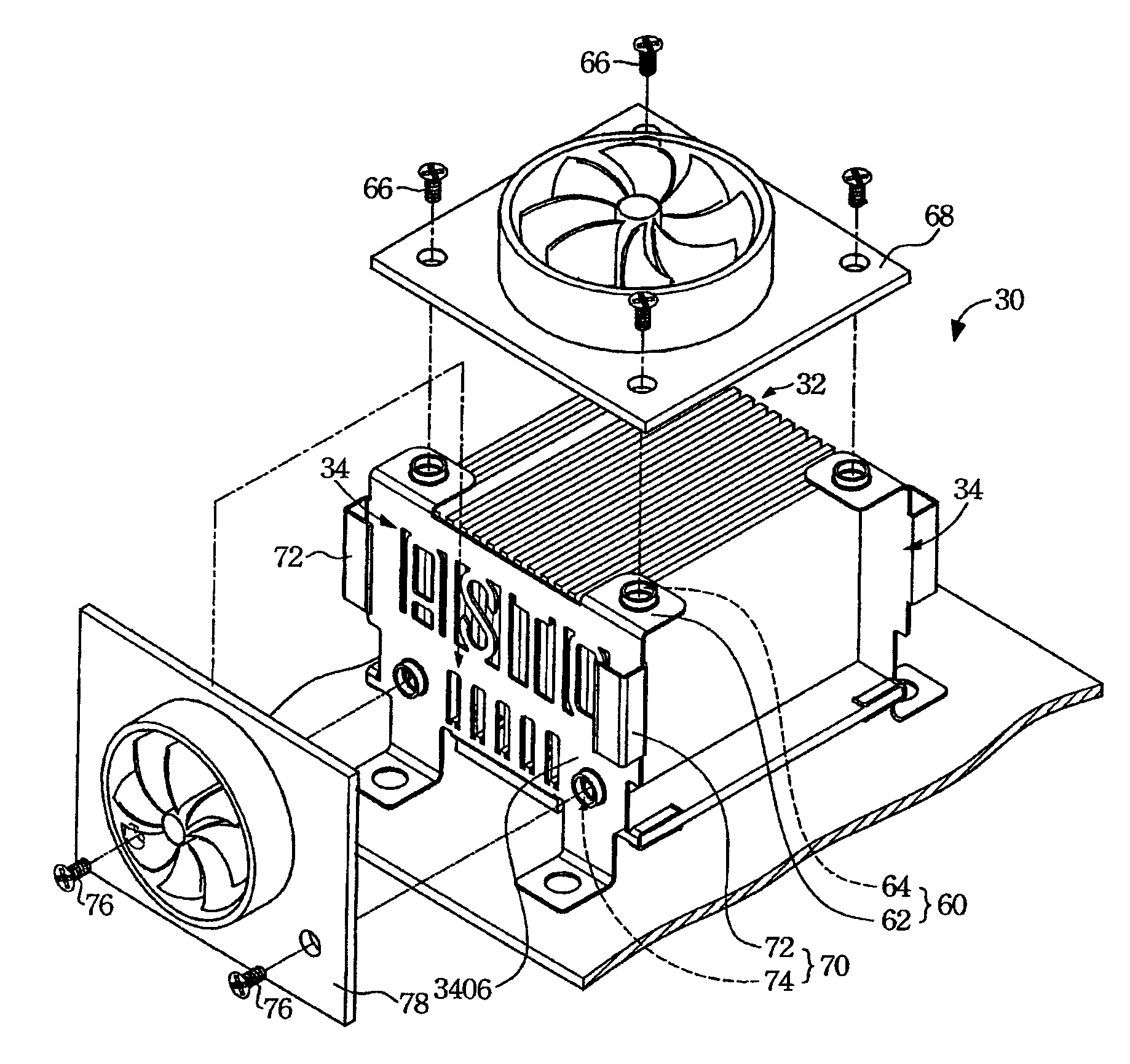
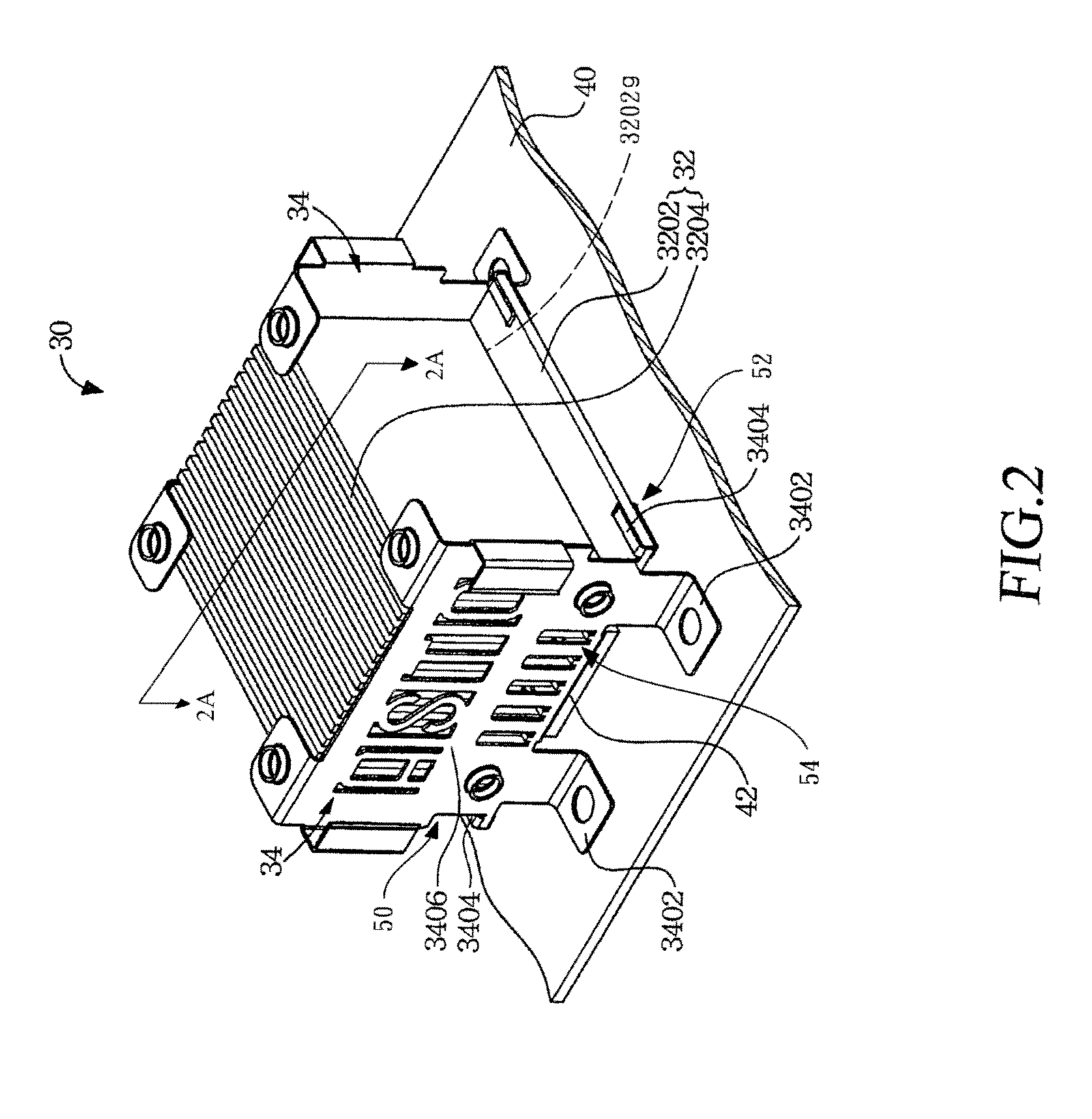
[0022]Please refer to FIGS. 2 and 2A which respectively illustrate a perspective view and a cross sectional view of a graphite heat dissipation apparatus 30 of the present invention. The present invention relates to the graphite heat dissipation apparatus 30 and at least one clamping frame 34 for clamping a graphite heat dissipation fin module 32. The graphite heat dissipation apparatus 30 includes the graphite heat dissipation fin module 32 and at least one clamping frame 34.

[0023]The graphite heat dissipation fin module 32 includes a substrate 3202 and a plurality of graphite fins 3204. The graphite fins 3204 are positioned at one surface of the...


PUM


Abstract

A graphite heat dissipation apparatus and a clamping frame for clamping a graphite heat dissipation fin module are provided. The graphite heat dissipation apparatus includes a graphite heat dissipation fin module and at least one clamping frame. The graphite heat dissipation fin module includes a substrate and a plurality of graphite fins which are positioned at and extend from one surface of the substrate. The clamping frame includes at least one support bracket, at least one retention plates and a frame body. The support brackets are positioned at top surface of a chassis. The frame body upwardly extends from the support brackets, and the retention plates traverse extend across the side surface of the frame body. The retention plates are used to clamp the substrate so that the graphite fins are positioned above the chassis. The graphite heat dissipation fin module is used to draw hear away from the electronic device which can be positioned below the substrate and at the surface of the chassis.

Description

BACKGROUND OF THE INVENTION[0001]1. Field of the Invention[0002]The present invention relates to a graphite heat dissipation apparatus, and in particular to a clamping frame for clamping a graphite heat dissipation fin module.[0003]2. Description of Related Art[0004]Please refer to FIG. 1 which illustrates a graphite heat dissipation apparatus 2 in prior art. As shown in FIG. 1, the graphite heat dissipation apparatus 2 draws heat away from an electronic device 6 such as processor or chipset which generates heat by a graphite heat dissipation fin module 4. The electronic device 6 is installed on the surface of a chassis 8 such as a printed circuit board. The graphite heat dissipation fin module 4 is attached to the top of the electronic device 6 to carry heat away from the electronic device 6. The graphite heat dissipation apparatus 2 is usually apparent at personal computers or servers and a much more advanced cooling method.[0005]Furthermore, the graphite heat dissipation apparatu...

Claims


Application Information

Patent Timeline
Patent Type & Authority Patents(United States)
IPC IPC(8): H05K7/20H01L23/467
CPCF28F3/02F28F21/02H01L23/373H01L23/467H01L2924/0002H01L2924/00
Inventor HORNG, CHIN-FU
Owner HORNG CHIN FU
Why Eureka
Try Eureka