Apparatus for temporarily holding logs within cutting-off machines

Inactive Publication Date: 2009-11-17
PERINI
View PDF20 Cites 9 Cited by
  • Summary
  • Abstract
  • Description
  • Claims
  • Application Information

AI Technical Summary

Benefits of technology

[0014]The present invention makes it possible to operate an effective and safe hold of the logs during the cutting step, and to ensure, also thanks to the rigidity of the components that make up the apparatus, the highest readiness in the response to the commands given by the actuators in charge of the operation of the holding means. Besides, owing to the particular handling of the pressers, the apparatus can aut

Problems solved by technology

However, the traditional pressers result inadequate to the current production requirements, both in terms of re

Method used


Image

  • Apparatus for temporarily holding logs within cutting-off machines
  • Apparatus for temporarily holding logs within cutting-off machines
  • Apparatus for temporarily holding logs within cutting-off machines

Examples


Embodiment Construction

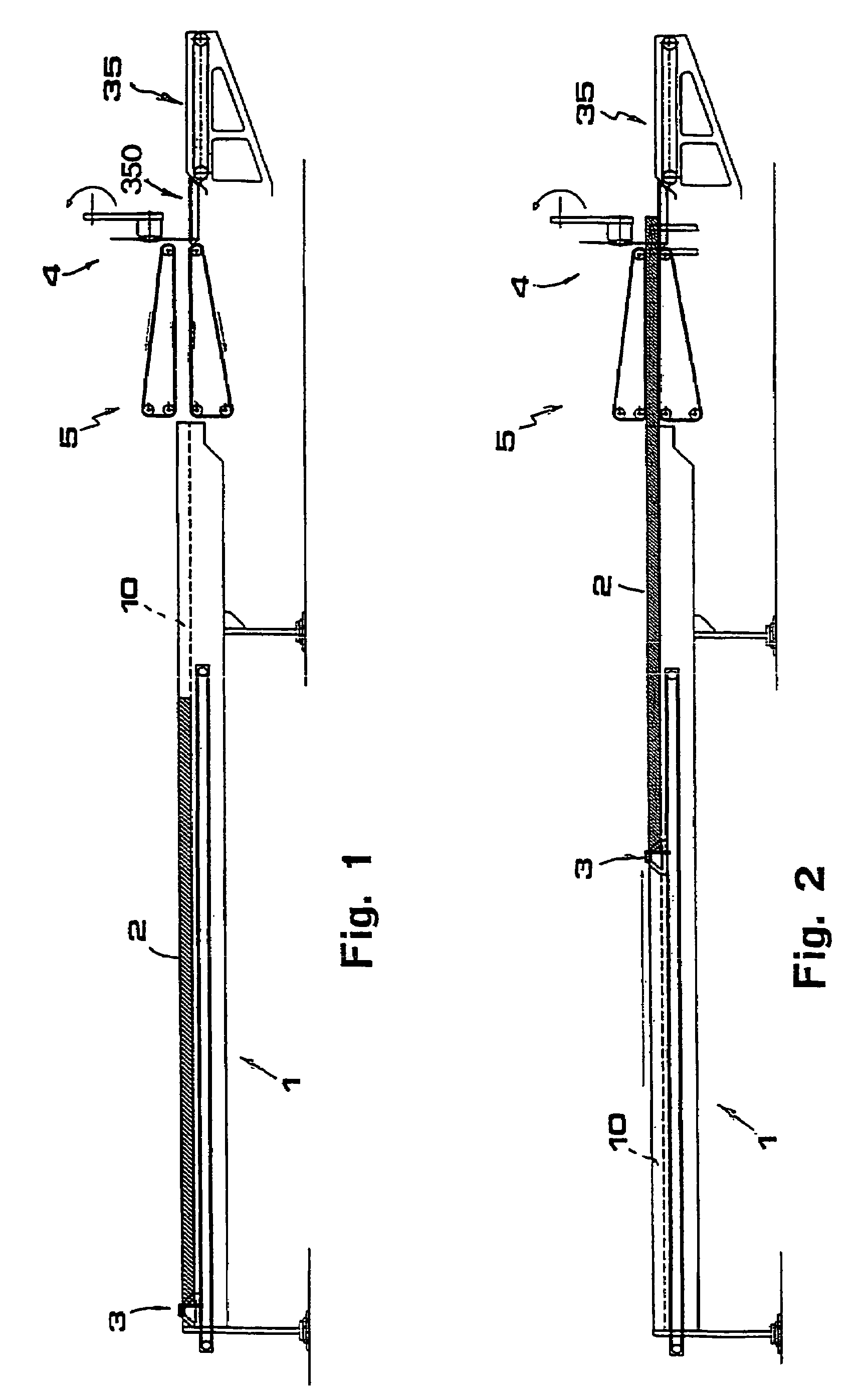
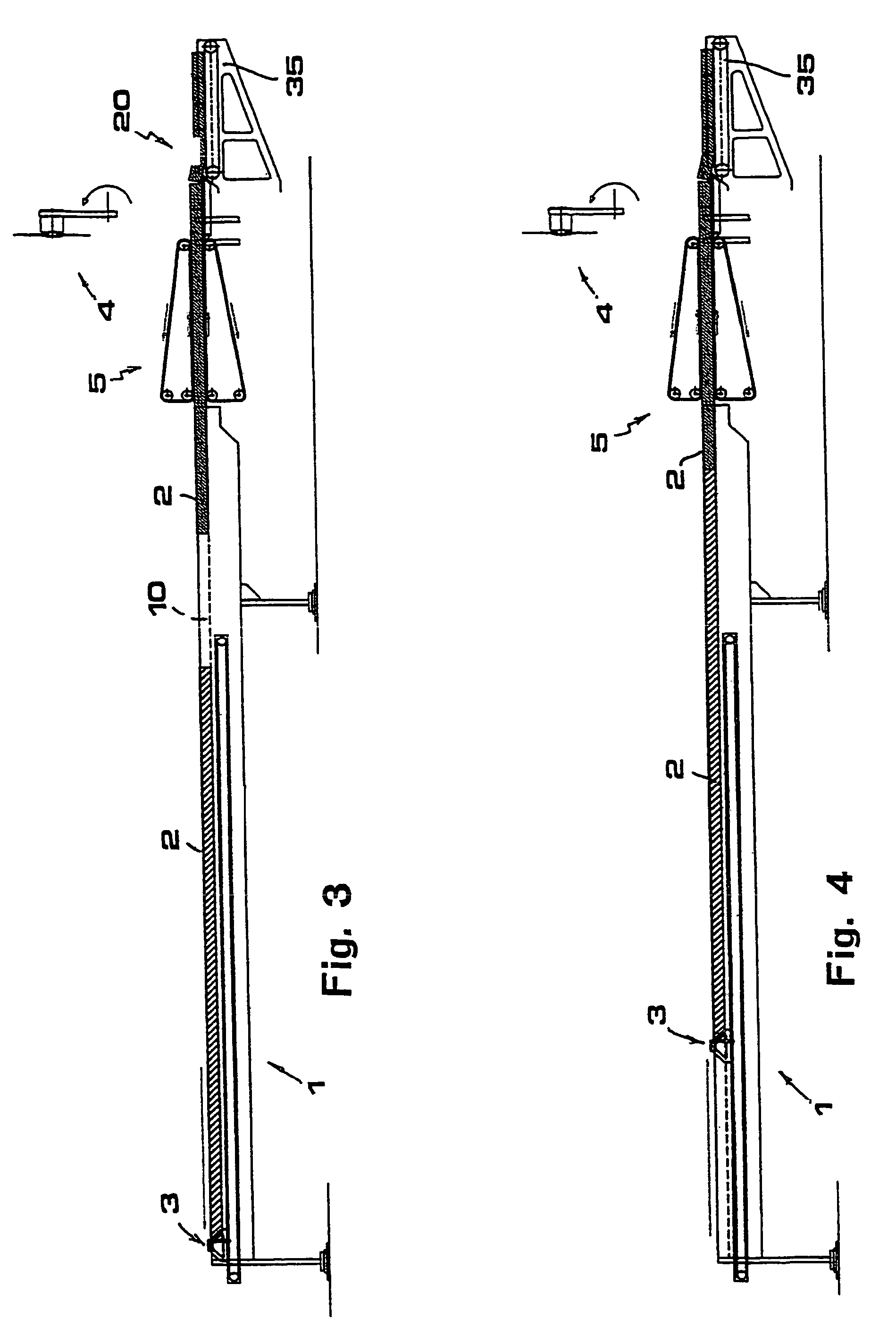
[0028]The present invention will be described herebelow, with reference to the figures of the attached drawings, as applied to a device for moving the logs toward the cutting station, comprising:[0029]a platform (1) with one or more longitudinal channels (10) inside which the logs to be cut are disposed;[0030]pusher means (3) acting in correspondence of said platform (1) and intended for acting on the back of the logs (2) to push them, along the respective guide channels (10), toward cutting means (4) disposed downstream;[0031]clamping means (5) disposed intermediate between said pusher means (3) and said cutting means (4) and intended for engaging the logs (2) which are pushed along the channels (10) of platform (1) by the pushers (3) and driving them along as far as said cutting means (4).

[0032]The said pusher means (3) comprise a bar (30) disposed transverse to the channels (10) of platform (1) and moved to and from the said clamping means (5) by a carriage (31) associated with a...


PUM


Abstract

An apparatus for temporarily holding logs within cutting-off machines including two plates (60), each of which exhibits a plurality of pressers (61) and an appendix sliding within a guide (7). The plates (60) are associated with an actuator (8) which drive them, under control, in a substantially straight movement in the direction of the relevant guides (7). The pressers are disposed in mirror-like and parallel relationship to each other, that is, orthogonally to the logs (2) to be treated.

Description

BACKGROUND OF THE INVENTION[0001]The present invention, refers to an apparatus for temporarily holding logs within cutting-off machines.[0002]In the following text, the term “logs” is meant to indicate rolls of web material (such as paper) wound up around a support core (for example, a tubular cardboard core), to be cut to form rolls of smaller length, that is, of commercial size.[0003]At present, the production of paper rolls is known to involve cutting transversally the logs, produced by a rewinding machine, by using one or more cutting-off machines.[0004]A cutting-off machine for logs is described in details in the patent IT-1247330.[0005]Essentially, a cutting-off machine of this type comprises:[0006]a plurality of channels or guides into which the logs are discharged and in correspondence of which movable devices, so-called “porters” in jargon, are mounted to drive the logs into longitudinal motion by pushing them from behind;[0007]a cutting station, comprising one or more circ...

Claims


Application Information

Patent Timeline
IPC IPC(8): B27C9/00B27L3/00B27L5/00B27L9/00B27M3/00B26D7/02B26D7/06
CPCB26D7/02B26D7/0683B26D2210/11B26D2007/013
Inventor PERINI
Owner PERINI
Why Eureka
Try Eureka