Elevator door system

a technology for elevator doors and doors, applied in the direction of door/window protective devices, curtain suspension devices, shutters/movable grilles, etc., can solve problems such as damage to the aesthetic appearance of doors

Inactive Publication Date: 2009-11-17
INVENTIO AG
View PDF41 Cites 4 Cited by
  • Summary
  • Abstract
  • Description
  • Claims
  • Application Information

AI Technical Summary

Benefits of technology

[0005]An objective of the present invention is to substantially reduce, and preferably cancel completely, the lateral driving forces transferred to the door from the motor during operation.
[0006]This objective is achieved by an elevator door system comprising a motor, a vertical axis rotatably driven by the motor, and an elevator door which, in operation, is wound upon and unwound from the vertical axis. The door is mounted to a flexible force transmission member that is provided along an entire width of the door and is interconnected to the vertical axis. The flexible force transmission member is capable of transmitting both tensile and compressive force. Accordingly, the forces generated by the motor for opening and closing the door are transmitted through the or each transmission member rather than being imparted onto the door itself as in the prior art door systems. Hence, in use the strain on the door is greatly reduced and therefore the quantity of material used for the door and consequently its cost and mass can be reduced without deteriorating performance.
[0007]Preferably, the flexible force transmission member projects horizontally outwards from the door. Accordingly, on opening, as the door is wound upon the vertical axis, the flexible force transmission member prevents direct contact between successive layers of the door thereby reducing noise and damage. Preferably, the force transmission member is sufficiently flexible so as to adapt to the profile of vertical axis as it is wound onto the vertical axis. This ensures a smooth and continuous engagement between the flexible force transmission member and the vertical axis which greatly reduces the generation of noise or vibration. The flexible nature of the force transmission member will also suppress the transmission of any vibration or noise to the door during operation.
[0008]Preferably, a first flexible force transmission member is provided at an upper edge of the door and a second flexible force transmission member is provided at a lower edge of the door. In use, the transmission members may be concealed from passengers within upper and lower guide channels, thereby not disrupting the regular visual appearance of the door.
[0009]Preferably, both transmission members extend horizontally outwards from both surfaces of the door. With this arrangement, the noise generated as successive sections of the door enter and engage with the guide channels is dampened since each transmission member is positioned between the door and the respective guide channel thereby preventing the door from coming into direct contact with the upper and lower guide channels during movement.
[0015]Preferably, a separation means is disposed between the door and the flexible force transmission member to separate the door from the transmission member to enable substantially friction-free relative rotation therebetween.

Problems solved by technology

Furthermore, in the prior art elevator door systems discussed above the wrapping of the door in layers about the vertical axis can give rise to unwanted noise due to contact between the successive layers and continual winding and unwinding of the door about the reel may cause frictional contact between successive layers which may eventually cause damage to the aesthetic appearance of the door.
As the Velcro™ belts cannot transmit compressive force, the shutter system of FR-A-2664324 suffers from the same disadvantage of the prior art mentioned above in that it must be capable of withstanding the compressive lateral driving forces transferred to it from the motor.

Method used


Image

  • Elevator door system
  • Elevator door system
  • Elevator door system

Examples


first embodiment

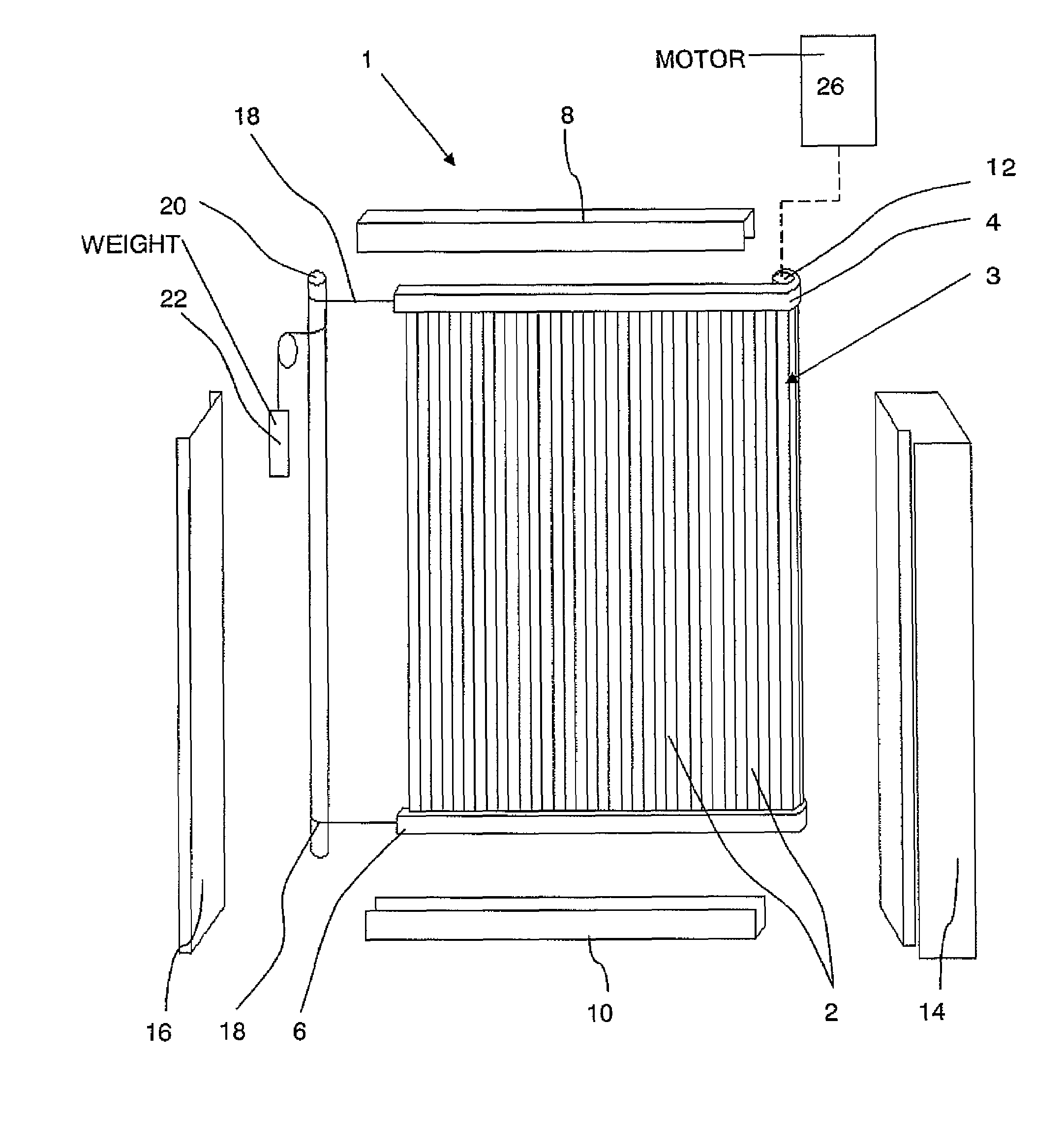
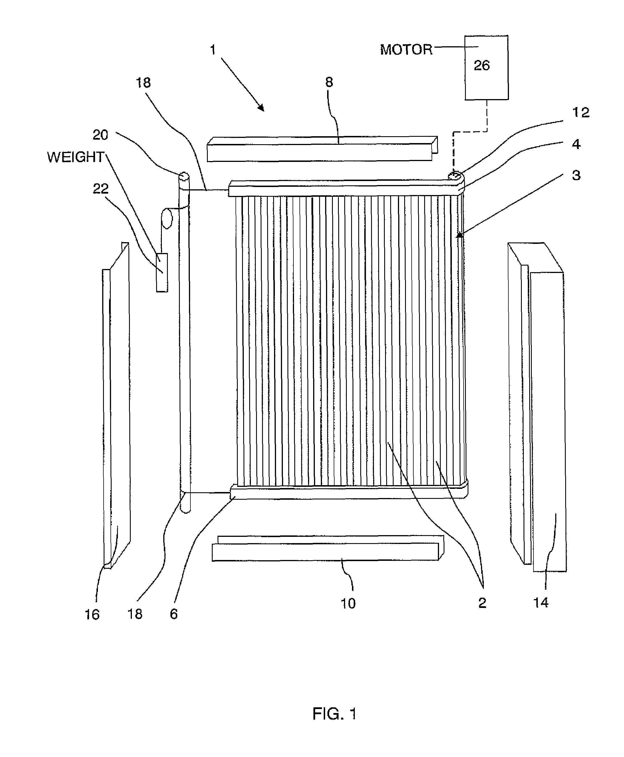
[0023]FIG. 1 is a general exploded perspective view of an elevator door system 1 incorporating a car door 3 according to the present invention which is used to control access to an elevator car (not shown) from a landing within a building. The door 3 is composed of a plurality of vertically aligned panels 2 each of which is preferably extruded from aluminium for its superior strength to weight ratio. The panels 2 are bound at their extremities by an upper belt of plastic material 4 and a lower belt of plastic material 6, respectively. The belts 4, 6 are attached at one end to a reel 12, rotation of which is controlled by a motor 26 to open and close the door 3. The opposing ends of the belts 4, 6 are attached by cables 18 to a counter-reel 20 which is biased in a door closing direction by a closing weight 22. The reel 12 and the counter-reel 20 are contained and retained within opposing door jambs 14 and 16, respectively.

[0024]During operation, the belts 4, 6 are guided along an upp...

third embodiment

[0032]FIG. 4 is partial perspective view of an elevator door according to the present invention wherein the constituent panels 2 of the door 3 of the previous embodiments are replaced by pairs of glass panels 38 embedded in, affixed or bonded to either side of a plasticized interlayer 36 of polyvinylbutyral (PVB) material. The interlayer 36 is suspended between the upper belt 4 and the lower belt 6 respectively. Preferably, the upper and lower belts 4, 6 are manufactured integrally from the same PVB material as the interlayer 36.

fourth embodiment

[0033]FIG. 5 and FIG. 6 illustrate components of an elevator door system according to the present invention. Although the drawings and the following description refer only to the lower guide channel 10 and a lower transmission belt 40, it will be readily appreciated that the guidance at the upper section of the door 3 is achieved in the same manner.

[0034]As in the previously described embodiments, one end of the belt 40 is secured to the reel 12 and the other end is connected by the cable 18 to the counter-reel 20 as shown in the general arrangement of FIG. 1. Rather than the rectangular profile of the previous embodiments, the lower belt 40 used in this embodiment has a cropped V-shape. During operation, the belt 40 is guided by pulleys 44 rotatably mounted in the lower guide channel 10 and having converging flanges which engage with the side walls of the V-belt 40 to provide the necessary horizontal and vertical guidance.

[0035]Each of the door panels 2 is provided with one or more...


PUM


Abstract

An elevator door system includes a motor rotating a vertical reel, and an elevator door. The door can be formed of a plurality of vertically aligned rigid panels or can be a sheet of material which is rigid or reinforced in the vertical direction or can have any other appropriate form making it suitable for being wound upon and unwound from the reel. The door is mounted to a flexible force transmission member provided along an entire width of the door and interconnected to the reel. Accordingly, the forces generated by the motor for opening and closing the door are substantially transmitted through the transmission member rather than being imparted onto the door itself. Hence, in use the strain on the door is greatly reduced and therefore the quantity of material used for the door and consequently its cost and mass can be reduced without deteriorating performance.

Description

BACKGROUND OF THE INVENTION[0001]The present invention relates to elevator doors systems and, in particular, to an elevator door system comprising a door that is wound upon a vertical axis during an opening operation.[0002]Such elevator door systems are well known from the prior art and are described, for example, in WO-A2-2005 / 070807 and WO-A2-2005 / 070808. Each elevator door is generally formed from a stainless steel sheet or interconnected vertical rigid panels, typically manufactured from a metal. In operation, as the elevator door is opened and closed, the plurality of panels or sheet is wound onto and unwound from a vertical axis in the form of a motorized reel whereby the driving force from the motor is transmitted through the reel and onto the door to provide lateral movement thereof. Hence, not only does the door need sufficient strength to withstand a specific transverse force applied perpendicular to the plane of the door without exceeding the maximum permissible elastic d...

Claims


Application Information

Patent Timeline
Patent Type & Authority Patents(United States)
IPC IPC(8): E06B9/08
CPCB66B13/08B66B13/06B66B13/14
Inventor SPIESS, PETER A.
Owner INVENTIO AG
Why Eureka
Try Eureka