Magnetoresistive flux focusing eddy current flaw detection

a magnetic field and focusing technology, applied in the direction of magnetic properties, instruments, material magnetic variables, etc., can solve the problems of airframe wings, detection of deeply buried flaws at airframe fasteners, and serious problems in the application of ultrasonic inspection methods, so as to achieve effective detection of deep flaws in thick multilayer conductive materials, high magnetic field sensitivity, and high flux density

Inactive Publication Date: 2005-05-03
NASA
View PDF16 Cites 35 Cited by
  • Summary
  • Abstract
  • Description
  • Claims
  • Application Information

AI Technical Summary

Benefits of technology

[0016]According to the present invention, the foregoing and other objects and advantages are attained by providing a giant magnetoresistive eddy current device that effectively detects deep flaws in thick multilayer conductive materials. The probe uses an excitation coil to induce eddy currents in conducting material perpendicularly oriented to the coil's longitudinal axis. A giant magnetoresistive (GMR) sensor, surrounded by an excitation coil, is used to detect generated fields. Between the excitation coil and the GMR sensor is a highly permeable flux focusing lens which magnetically separates the GMR sensor and excitation coil and produces high flux density at the outer edge of the GMR sensor. The use of feedback inside the flux focusing lens enables complete cancellation of the leakage fields at the GMR sensor location and biasing of the GMR sensor to a location of high magnetic field sensitivity. In an alternate embodiment, a permanent magnet is positioned adjacent to the GMR sensor to accomplish the biasing. Experimental results have demonstrated identification of flaws up to 1 cm deep in aluminum alloy structures.
[0017]The present invention is further directed to a magnetoresistive flux focusing eddy current device that effectively detects deep flaws about circular fasteners or inhomogeneities in thick multilayer conductive materials. A giant magnetoresistive flux focusing eddy current device, as described above, is mounted in a hand-held rotating probe assembly that is connected to a computer for system control, data acquisition, processing and storage.

Problems solved by technology

Nondestructive evaluation (NDE) technologies have recently been challenged to inspect thick, layered, conducting materials for fatigue and corrosion damage.
Structures that fall into this class, such as airframe wings, pose significant difficulties for conventional inspection techniques, and especially challenging is the detection of deeply buried flaws at airframe fasteners.
Reflections of ultrasound at layer boundaries cause serious problems for the application of ultrasonic inspection methods.
Conventional eddy current inspection techniques are also compromised due to the exponential decay of electromagnetic energy with depth into a conductor.
The sensitivity of the method, however, is severely limited as material thickness increases.
This reduction in frequency, however, limits the sensitivity of the inductive pickup sensor whose output is proportional to the frequency.
These devices, however, typically require substantial instrumentation and have sensitivities much lower than that of the GMR sensor.
Super Conducting Quantum Interface Devices (SQUIDS) have sensitivities better than the GMR devices but the requirement of cryogenic temperatures imposes difficulties in application and typically greatly increases the sensor size.
Flux Gate Magnetometers have sensitivities similar to GMR sensors and although they do not require a cryogenic temperature, they do require substantial instrumentation and typically relatively large probe size.
Ultrasonic techniques have been shown to be useful for detecting flaws in thick materials, but have limited success in multilayered structures due to reflection of the wave at the interfaces of the layers.
Thermographic techniques have difficulties with metallic and thick materials, and typically require greater amounts of instrumentation for application and data analysis.
X-ray methods pose environmental concerns and are not typically portable due to the large instrumentation requirements.
The device is very accurate for the detection of near surface fatigue cracks but the performance for deeper inspections is limited due to several features of the design, including flux leakage around the flux focusing lens and decreased detection sensitivity with lowered frequency.
The sensititivy of the Sliding Probe is often low and a preferred orientation of the probe may lead to false calls or undetected flaws for rivets which are not aligned in a row.
Template methods using pencil probes are very time consuming, and lift off or probe wobble can produce false signals.

Method used


Image

  • Magnetoresistive flux focusing eddy current flaw detection
  • Magnetoresistive flux focusing eddy current flaw detection
  • Magnetoresistive flux focusing eddy current flaw detection

Examples


Embodiment Construction

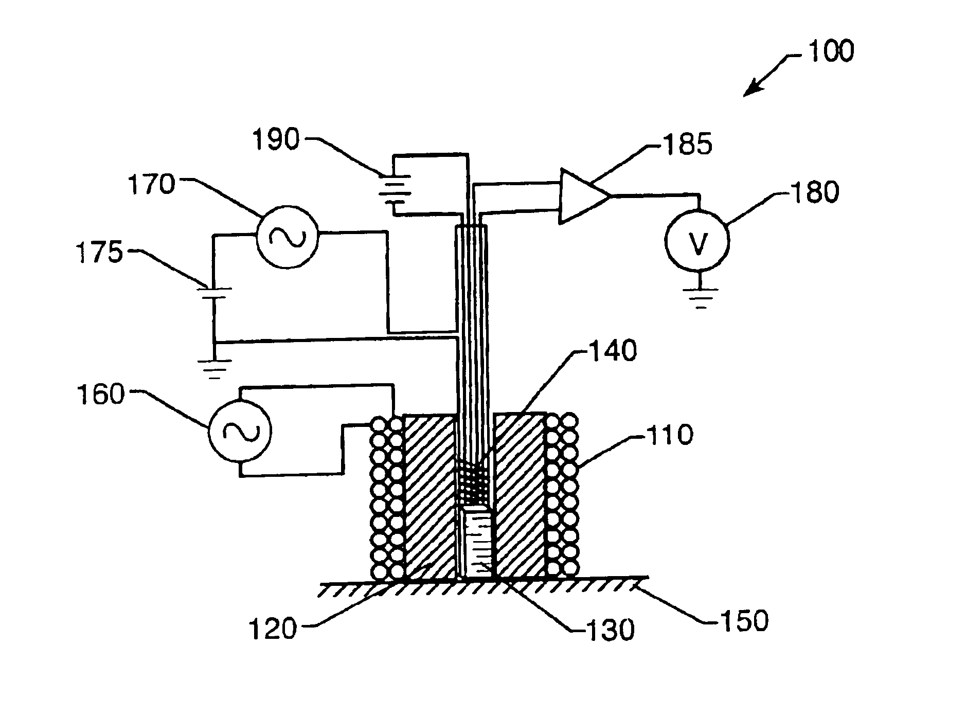
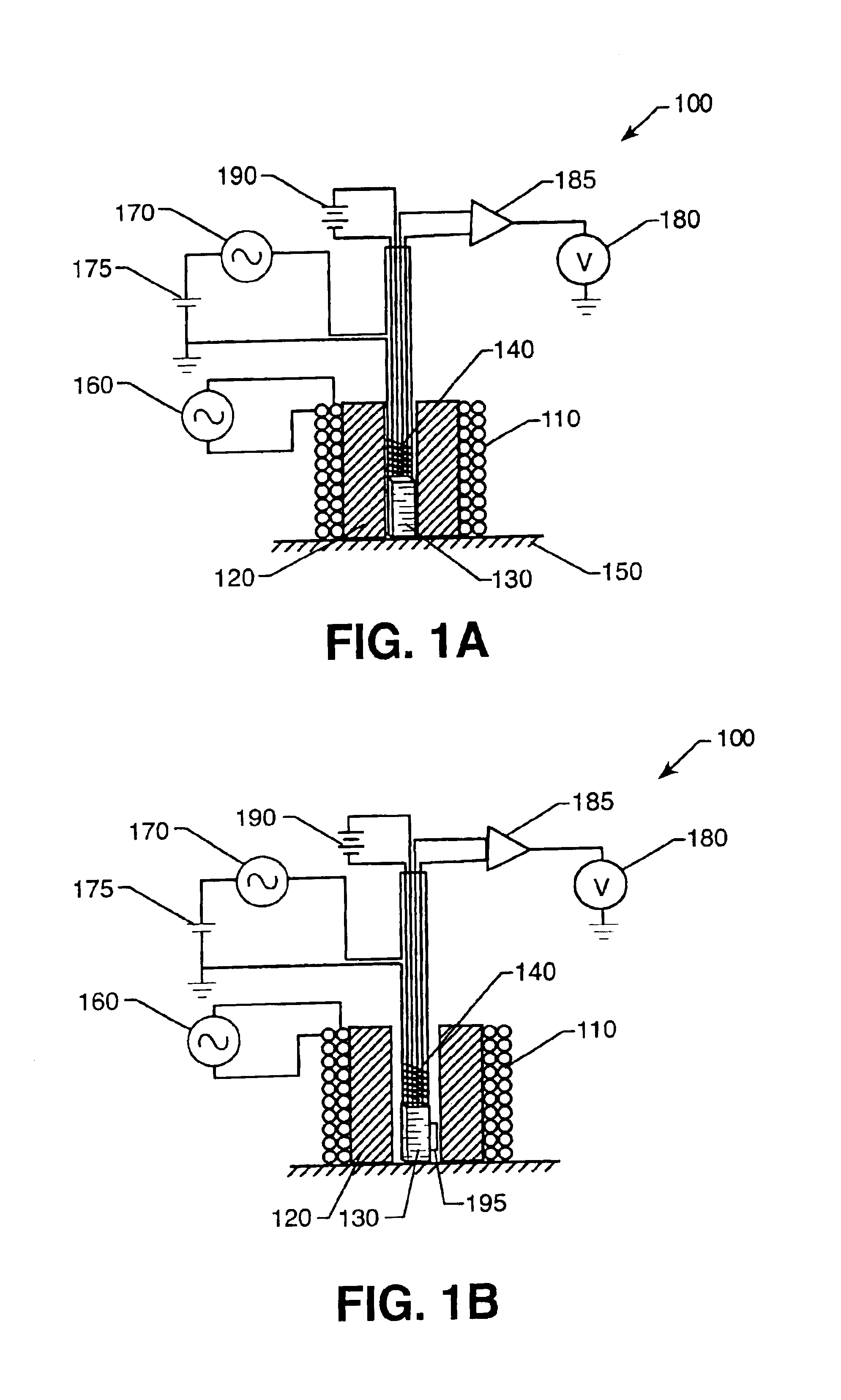
[0049]With reference now to FIG. 1A, wherein like numbers designate like components throughout all the several figures, the GMR sensor-based flux focusing eddy current probe of the present invention is particularly well adapted for non-destructive evaluation of electrically conductive thick materials having multiple layers and deep cracks. Although particularly useful for such detection, it may also be used effectively for closer-surface flaw detection. The probe generally designated at 100 includes an excitation (drive) coil 110, a flux focusing lens 120, a giant magnetoresistive (GMR) sensor 130, and a feedback coil 140. The probe 100 applies the eddy current principle to evaluate electrically conductive material 150 for faults. An alternating current supplied by a current source 160 electrically connected to the excitation coil 110 produces eddy currents within conductive material 150 placed in proximity with the probe 100. Voltage 190 is supplied to the GMR sensor 130. Magnetic ...


PUM

PropertyMeasurementUnit
thickaaaaaaaaaa
thickaaaaaaaaaa
frequencyaaaaaaaaaa

Abstract

A giant magnetoresistive flux focusing eddy current device effectively detects deep flaws in thick multilayer conductive materials. The probe uses an excitation coil to induce eddy currents in conducting material perpendicularly oriented to the coil's longitudinal axis. A giant magnetoresistive (GMR) sensor, surrounded by the excitation coil, is used to detect generated fields. Between the excitation coil and GMR sensor is a highly permeable flux focusing lens which magnetically separates the GMR sensor and excitation coil and produces high flux density at the outer edge of the GMR sensor. The use of feedback inside the flux focusing lens enables complete cancellation of the leakage fields at the GMR sensor location and biasing of the GMR sensor to a location of high magnetic field sensitivity. In an alternate embodiment, a permanent magnet is positioned adjacent to the GMR sensor to accomplish the biasing. Experimental results have demonstrated identification of flaws up to 1 cm deep in aluminum alloy structures. To detect deep flaws about circular fasteners or inhomogeneities in thick multilayer conductive materials, the device is mounted in a hand-held rotating probe assembly that is connected to a computer for system control, data acquisition, processing and storage.

Description

CLAIM OF BENEFIT OF PROVISIONAL APPLICATION[0001]Pursuant to 35 U.S.C. §119, the benefit of priority from provisional application 60 / 253,352, with a filing date of Nov. 28, 2000, is claimed for this non-provisional application.ORIGIN OF THE INVENTION[0002]The invention described herein was jointly made by an employee of the United States Government and by a contractor during the performance of work under a NASA contract and is subject to provisions of Section 305 of the National Aeronautics and Space Act of 1958, as amended, Public Law 85-568 (72 Stat. 435; 42 USC 2457).BACKGROUND OF THE INVENTION[0003]Nondestructive evaluation (NDE) technologies have recently been challenged to inspect thick, layered, conducting materials for fatigue and corrosion damage. Structures that fall into this class, such as airframe wings, pose significant difficulties for conventional inspection techniques, and especially challenging is the detection of deeply buried flaws at airframe fasteners. Reflecti...

Claims


Application Information

Patent Timeline
Patent Type & Authority Patents(United States)
IPC IPC(8): G01N27/90
CPCG01N27/9033G01N27/9006
Inventor WINCHESKI, RUSSELL A.NAMKUNG, MINSIMPSON, JOHN W.
Owner NASA
Why Eureka
Try Eureka