Multifunction unwinding device

a multi-functional, unwinding technology, applied in the direction of transportation and packaging, thin material processing, filament handling, etc., can solve the problems of reducing the overall productivity of the line, deteriorating the characteristics of the finished product, dust and deterioration, etc., and the operation of the unwinding device is extremely uncertain

Active Publication Date: 2009-11-17
FABIO PERINI SPA
View PDF26 Cites 15 Cited by
  • Summary
  • Abstract
  • Description
  • Claims
  • Application Information

AI Technical Summary

Benefits of technology

[0012]The object of the present invention is to produce an unwinding device which allows an expired reel to be replaced reliably with a new reel at speed, that is, by making the new reel rotate at a suitable peripheral speed, typically the same as the speed of the expiring reel, before splicing the two web materials and which also allows conventional operation, that is, replacement of the expired reel with a new reel and splicing of the tail and head of the web material in static conditions, allowing the operator to choose the required operating mode.
[0016]This makes the device very flexible, allowing the user to choose the most suitable type of operating mode for different circumstances, also as a function of the number of plies that the product obtained by processing the web materials delivered by the unwinding device is to be composed of.

Problems solved by technology

This operation reduces the overall productivity of the line with evident disadvantages in economic terms.
Although it is possible for a certain amount of web material to accumulate from the unwinder to the production line, for example using a festoon accumulator, this is not always advisable due to the characteristics of the web material, which may not have a particularly high tensile strength, or in view of the high speed of the production line, which would require an extremely large accumulator.
Moreover, the winding path defined by the festoon causes fibers to detach from the web material, especially when it is made of tissue paper, with the consequent production of dust and deterioration of the characteristics of the finished product.
Operation of this unwinding device is extremely uncertain as in the initial, most critical phase of feeding the new web material, drawing is entrusted to mere contact between two extremely light materials.
There is nothing to guarantee that the web material coming from the new reel will effectively follow the path defined by the first web material coming from the expiring reel.
The position of the cylinders which perform splicing of the two web materials must be in the position in which the head of the second web material is located at the time of splicing and not farther back, as otherwise the head of the web material would remain free and would accidentally wind around one or the rollers of the production line, thereby jamming the entire production line.

Method used


Image

  • Multifunction unwinding device
  • Multifunction unwinding device
  • Multifunction unwinding device

Examples


Embodiment Construction

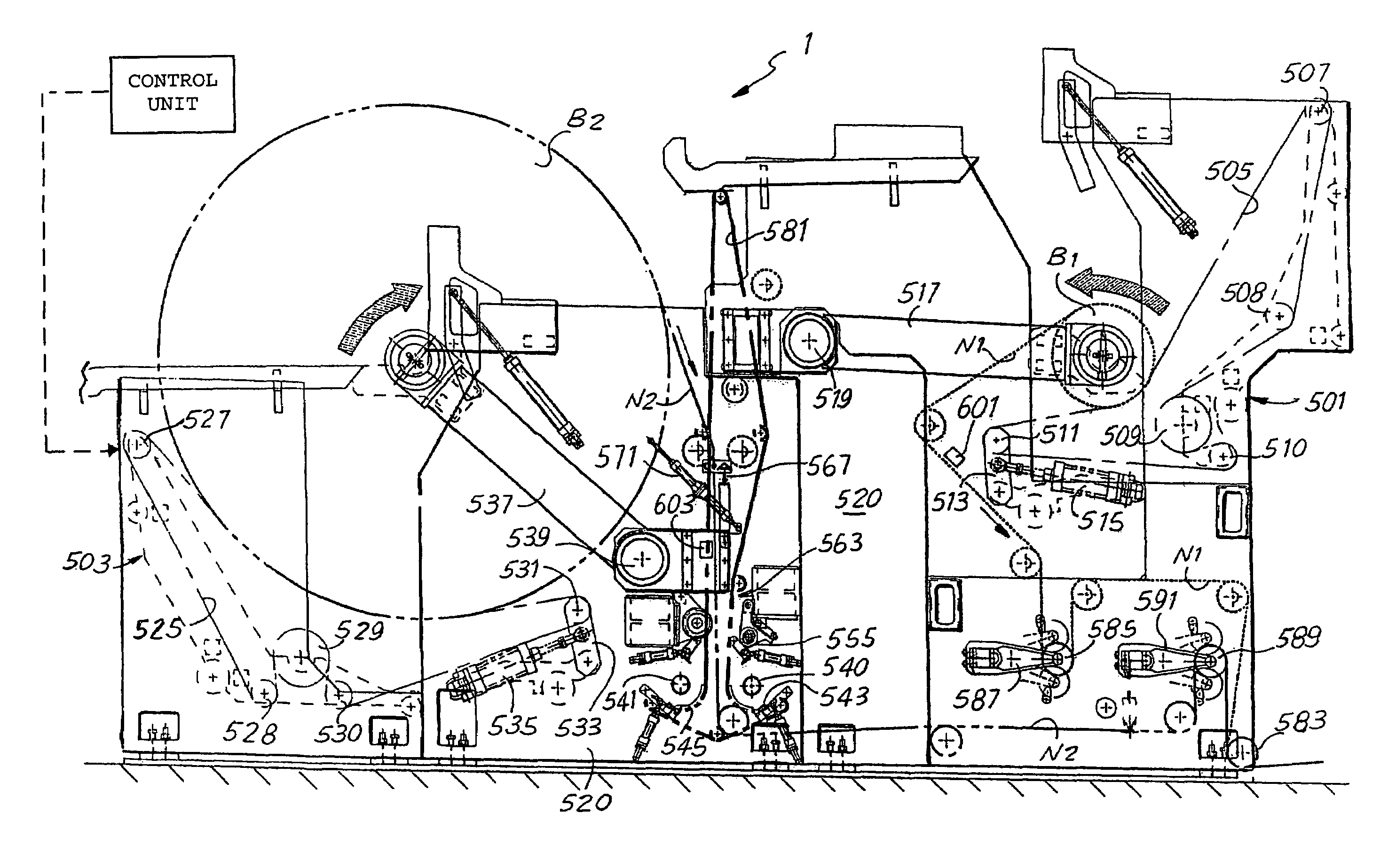
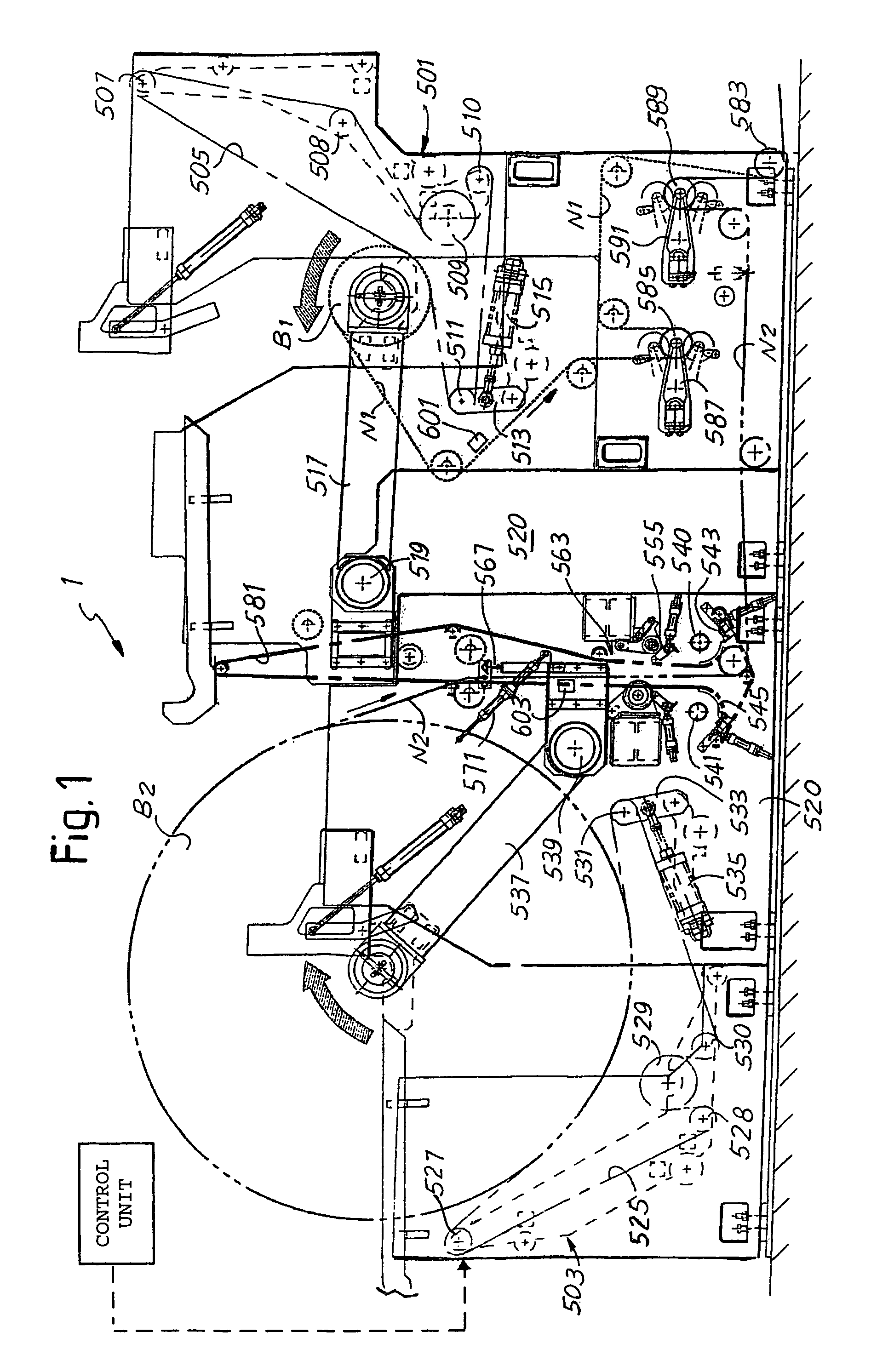
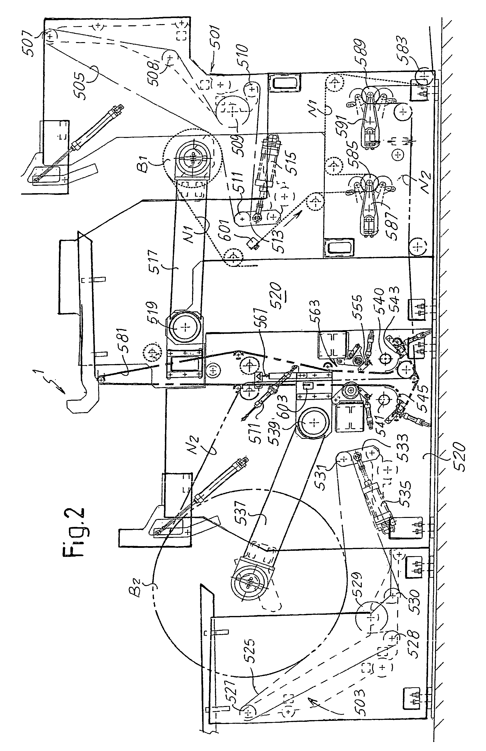
[0029]The device will be initially described in the complete structure thereof with reference to FIGS. 1 to 3 and subsequently two operating methods will be illustrated with reference to FIGS. 1 and 2 and to FIGS. 4 to 7 respectively.

[0030]In general, the unwinding device, indicated as a whole with 1, comprises a first unwinding member 501 and a second unwinding member 503 to unwind, simultaneously or in succession, two reels indicated with B1 and B2 in the drawing. The web material unwound from the reel B1 is indicated with N1 while the web material unwound from the reel B2 is indicated with N2. The unwinding member 501 comprises a system of belts 505 driven around pulleys 507, 508, 509, 510, 511. The pulley 509 is motorized while the pulley 511 is supported by an oscillating arm 513 operated by a piston-cylinder actuator 515, which holds the belt 505 in tension against the surface of the reel B1. Said reel is supported by a pair of arms 517 hinged in 519 to the load-bearing struct...


PUM


Abstract

The unwinding device to unwind reels of web material includes: unwinding members to simultaneously unwind a first reel and a second reel; a splicing device to join together a first web material coming from the first reel and a second web material coming from the second reel; at least one accumulation member to accumulate the web material delivered from the second reel before splicing with the web material delivered from the first reel; a first path and a second path for the web material delivered simultaneously from the first and from the second reel towards a machine downstream.

Description

TECHNICAL FIELD[0001]The present invention relates to an unwinding device to unwind reels of web material wound around a central axle to deliver web material to a converting or processing line.PRIOR ART[0002]In many industrial applications it is necessary to feed a web material to a production line, which is unwound from a reel or from several reels in parallel. Typically, feed of web material is required in the paper industry. For example, to produce paper napkins, rolls of toilet paper, rolls of kitchen towel or the like converting lines are provided wherein a web material is delivered from a reel with a large diameter and a high axial dimension to a series of downstream stations, at the end of which the finished product is obtained. In the case of rolls of toilet paper or similar products, the web material is delivered from one or more parent reels of large diameter and wound in rolls or logs of a smaller diameter, which are subsequently cut orthogonal to the axis thereof to obta...

Claims


Application Information

Patent Timeline
Patent Type & Authority Patents(United States)
IPC IPC(8): B65H19/18
CPCB65H19/1836B65H2408/216B65H19/18B65H19/10
Inventor GELLI, MAUROMADDALENI, ROMANOMORELLI, ROBERTO
Owner FABIO PERINI SPA
Why Eureka
Try Eureka