Equipoising support apparatus

a support apparatus and equipment technology, applied in the field of equipment supports, can solve the problems of reducing the load, compromising isoelasticity, and affecting the operation of the operator, and achieve the effect of reducing the weight of the operator's equipment, reducing the load, and maximum torsional stiffness

Active Publication Date: 2009-11-17
BROWN GARRETT W
View PDF66 Cites 45 Cited by
  • Summary
  • Abstract
  • Description
  • Claims
  • Application Information

AI Technical Summary

Benefits of technology

[0018]In a first, aspect of an illustrative embodiment of the invention, a force-exerting and / or lifting triangle, which provides the lifting power for the support arm, comprises a long side and a short side pivotally connected at a variable angle, with a resilient member pivotally forming another side of the triangle so as to bias the angle appropriately for the purpose of equipoising the payload. The efficiency of the lifting triangle can be improved in two ways: 1) by pivoting the short side of the lifting triangle to a optimal offset angle with reference to vertical and 2) by an additional, dynamic angular alteration of the verticality in response to the raising or lowering of the long side of the lifting triangle.
[0038]Embodiments of the invention provide the features described in the two paragraphs immediately above by including a support arm for the camera stabilizing device that comprises a parallelogram linkage that is biased upward by a unitary, extendable and retractable resilient member, one end of which may be selectably raised or lowered along a preferably curved member mounted with respect to a pivot that is preferably common with a pivot of the parallelogram. The resilient member termination path can be additionally, arcuately adjusted, both fixedly and dynamically by a cam, crankshaft linkage, or the like, so that the resilient member attachment point can be swung inwardly and outwardly with respect to a vertical parallelogram side so as to dynamically alter the effective lifting power of the resilient means. Irregular cam shapes are also contemplated and within the scope of the invention to more particularly contour the lifting profile to produce appropriate arm performance.

Problems solved by technology

These arms rely to a greater or lesser extent on friction to retain a set angle or position, since existing spring geometries do not necessarily provide appropriate or consistent lift throughout the entire angular excursion of the parallelogram links.
In practice it was found that when the support of lighter cameras required relaxing the tension of the spring series, the spring rate became inappropriate for those reduced loads and iso-elasticity was compromised.
Further, this three-spring solution was complex and expensive, requiring a plurality of pulleys and robust cables.
In practice, the arm embodying the technology claimed in the '196 patent was found to be somewhat frictional due to the ‘gear ratio’ of the differential pulley.
Also, the closer iso-elasticity was achieved, the more erratic was the arm's behavior at the extremes of high and low lifting position.
The angle of the line was fixed, however, and since only its lateral displacement could be adjusted, its effect inappropriately increased rather than decreased the lifting efficiency where it was most needed—as the spring termination point was lowered.
Even with a degree of control over iso-elasticity, parallelogram arms were still prone to unexpected and forcible closure as angles neared 60° above or below horizontal.
This is partly a consequence of the unpredictably varying torques imposed by the cantilevered, gimbaled payloads that hang at various angular positions relative to the arm parallelogram.
The result has been an uncontrollable tendency to lock up, or lurch ‘over-centers’, at the high or low position, and so various bumper designs have, in some cases, restrained the travel to as little as 45° above level.
In no case were the angular extremes of lift available from such parallelograms, and thus the lifting range of travel of the arms was curtailed.
In addition, bumpers “bumped” more or less suddenly and further caused operators to be wary of approaching them—which further limited the usefulness of these support arms.
Limitations in the Flyer arm, however, were evident at extremes of high lift.
Parallelograms are capable of closing to nearly ±80°, but have previously been unusable at those angles due to the foregoing problems, despite various bumper schemes employed to tame these extreme up / down positions.

Method used


Image

  • Equipoising support apparatus
  • Equipoising support apparatus
  • Equipoising support apparatus

Examples


Embodiment Construction

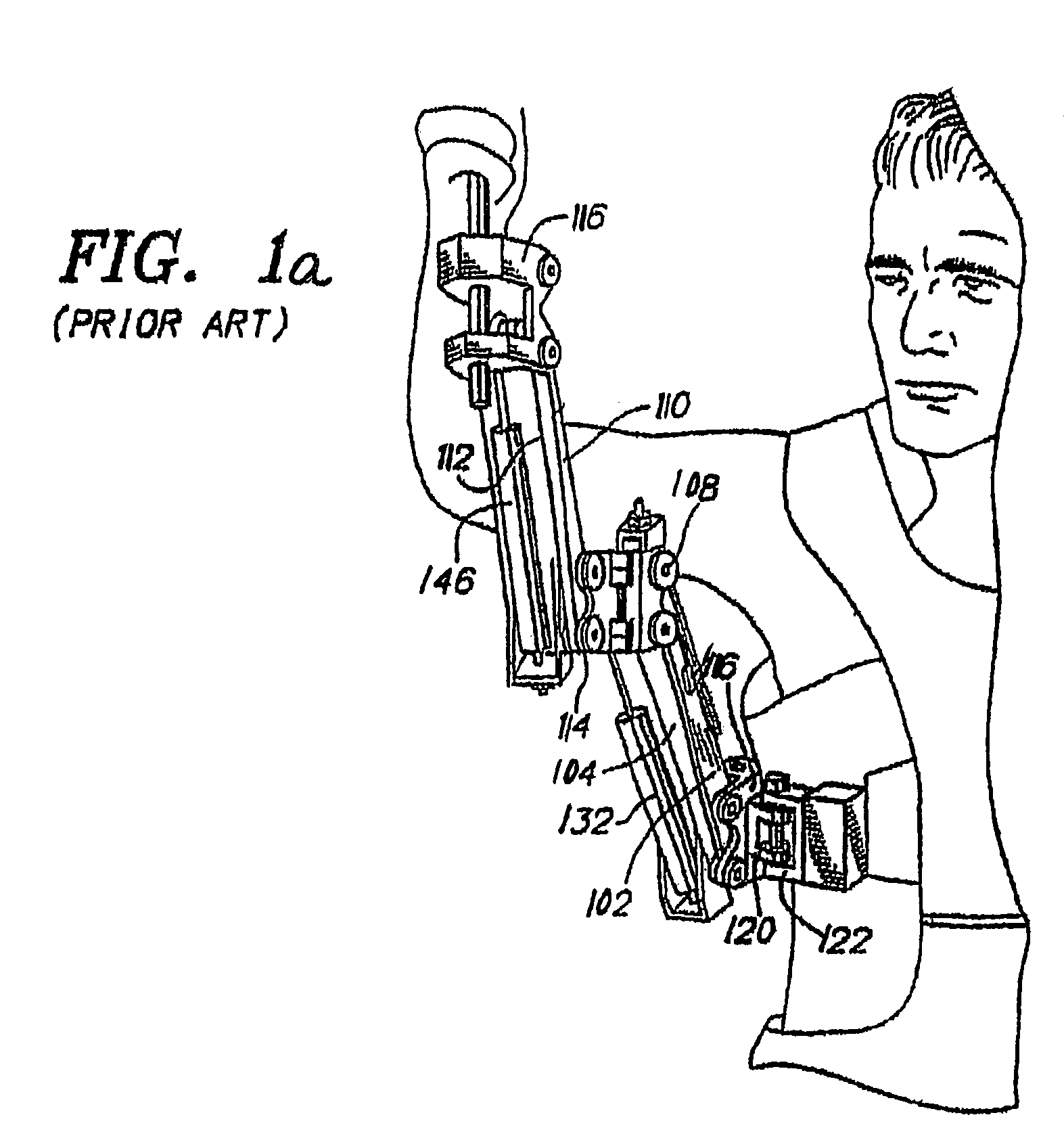
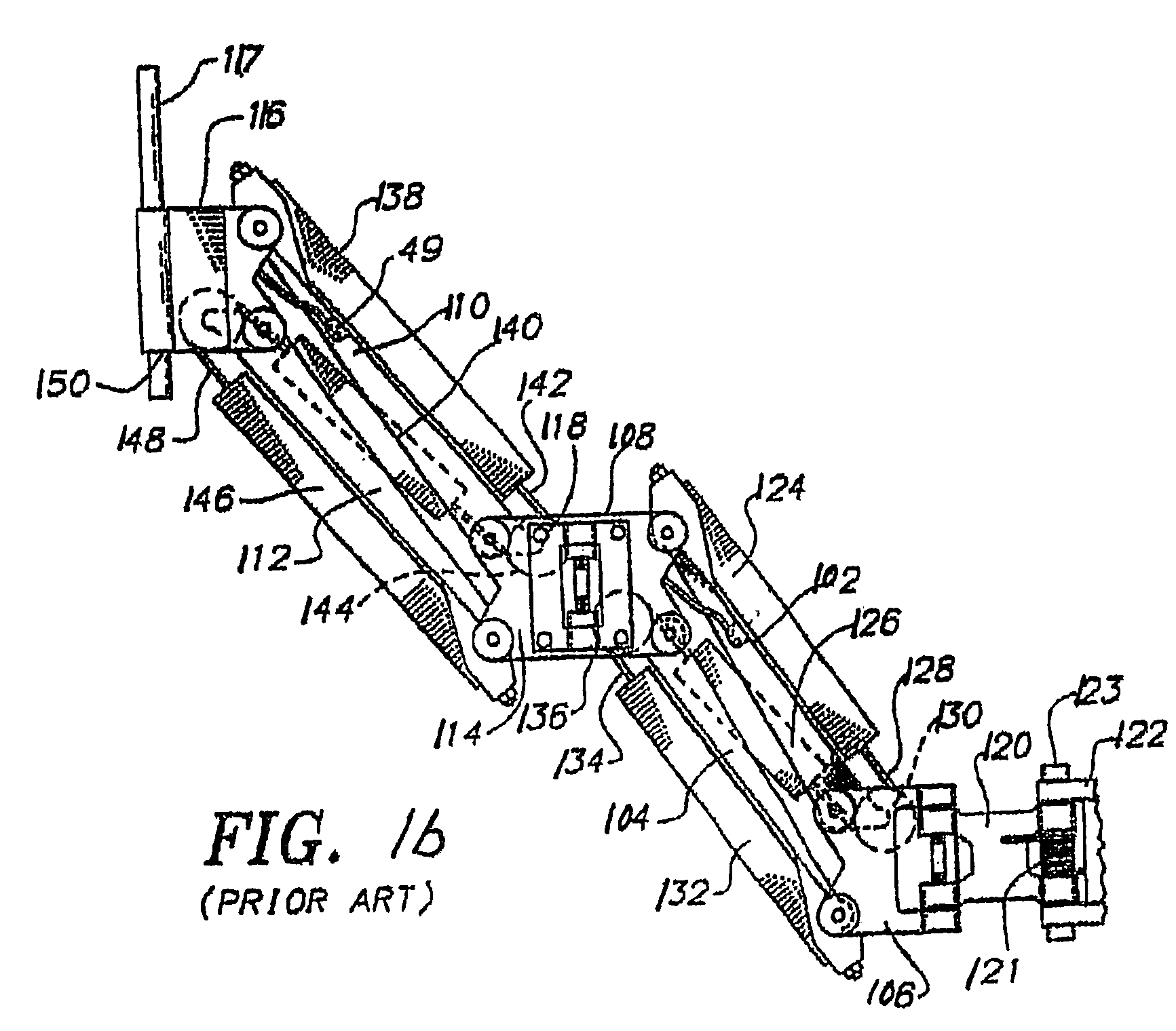
[0057]FIGS. 1a, 1b and 2 illustrate a support apparatus of the prior art, which the inventor originally devised to obtain stabilized motion picture film and video images and which was offered for sale under the trademark “Steadicam®”. As illustrated, the support arm for the apparatus includes a pair of parallel upper arms links 102, 104, which are pivotally coupled at one end to a connector hinge bracket 106. The other ends of the upper arm links 102,104 are pivotally coupled to an upper arm medial hinge bracket 108. A second pair of parallel forearm links 110, 112 is pivotally coupled between a forearm medial bracket 114 and a camera support bracket 116. A camera mounting pin 117 is provided in the camera support bracket 116.

[0058]The upper arm medial bracket 108 and the forearm medial bracket 114 are rotatably coupled together along one side by a hinge 118. The connector hinge bracket 106 is rotatably coupled at its center to one end of a lower support hinge plate 120. The other e...


PUM


Abstract

A force exerting device having a force exerting structure including a load arm as a first side, pivotable about a load pivot, a resilient member attached to the load arm and to a termination point and forming a second side of the force exerting structure. The third side of the structure is formed by a line from the termination point to the load pivot. A first adjustment mechanism moves the termination point to change the length of the third side of the structure. A second adjustment mechanism moves the termination point in a direction different than the first adjustment direction so the termination point location can cross a substantially plumb line passing through the load pivot. A force modification device may be included to dynamically adjust the resilient member termination point position in response to motion of the load arm.

Description

[0001]This application is based on, and claims priority to, provisional application Ser. No. 60 / 672,186, having a filing date of Apr. 15, 2005, and entitled, Auto Adjusting Equipoising Support Apparatus.BACKGROUND OF THE INVENTION[0002]This invention relates generally to equipment supports, and more particularly to portable equipment utilized in conjunction with motion picture or video cameras.[0003]Mobile film or video cameras typically require angular and spatial stability in order to obtain smooth, high-quality results. The Steadicam® portable camera stabilizing device, which has become a de facto standard in the TV and movie industry, was developed to permit stable ambulatory videography or cinematography by an operator. The inventor's U.S. Pat. No. 4,017,168 (Re. 32,213), U.S. Pat. Nos. 4,156,512 & 4,474,439 are directed to aspects of such stabilizing devices.[0004]Spring powered ‘equipoising’ parallelogram arms have been used for decades to support and position payloads such a...

Claims


Application Information

Patent Timeline
Patent Type & Authority Patents(United States)
IPC IPC(8): F16M13/00E04G3/00G03B17/00
CPCF16F1/12F16M11/04F16M11/18F16M11/2014F16M11/2092G03B17/56F16M13/00F16M13/04F16M11/24F16M2200/044F16M2200/063G03B17/561G03B17/00
Inventor BROWN, GARRETT W.
Owner BROWN GARRETT W
Why Eureka
Try Eureka