Near field lens

a near field lens and lens body technology, applied in the field of near field lenses, can solve the problems of high power consumption, difficult optical design and manufacturing of light pipes, and difficult optical design of light pipes, so as to achieve the effect of improving optical efficiency, reducing optical efficiency, and reducing optical efficiency

Active Publication Date: 2009-11-17
VARROC LIGHTING SYST SRO
View PDF17 Cites 65 Cited by
  • Summary
  • Abstract
  • Description
  • Claims
  • Application Information

AI Technical Summary

Problems solved by technology

Styling themes demand light pipes having oddly curved shapes, which are optically challenging to design.
This increase in shape complexity of the light pipes makes both the optical design and manufacturing of the light pipe very difficult.
Light pipes that have complex shapes typically have lower optical efficiency and require high power LEDs to meet the Federal Motor Vehicle Safety Standards (FMVSS) beam pattern regulations.
This amount of light is insufficient for many designs.
However, if light pipe lengths or diameters need to be reduced, or if additional light needs to be added, cost and customer satisfaction may be impacted.
However, since many of the high powered LEDs come with optics (a “dome”) above the chip with 5-8 mm diameters, it is difficult to design an optical device that will accommodate both the LED optic and a light pipe having a small diameter (5-10 mm).

Method used


Image

  • Near field lens
  • Near field lens
  • Near field lens

Examples


Embodiment Construction

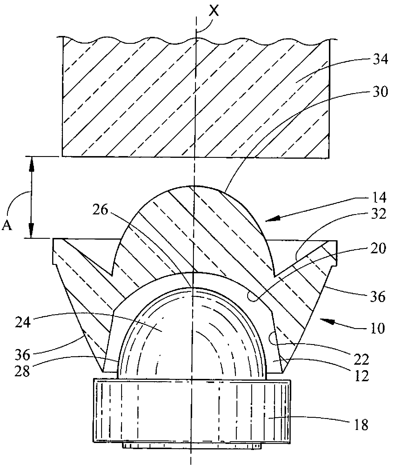
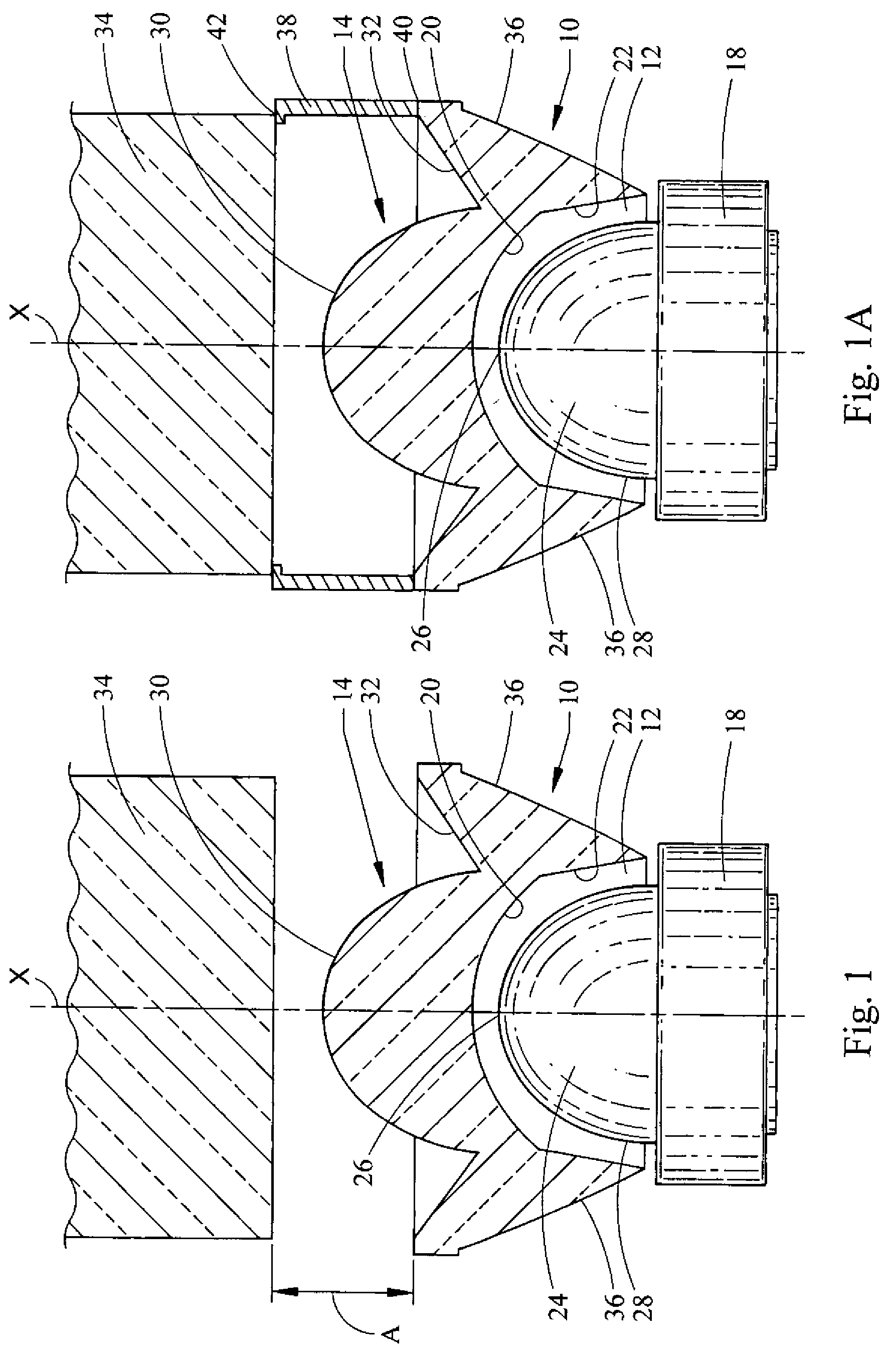
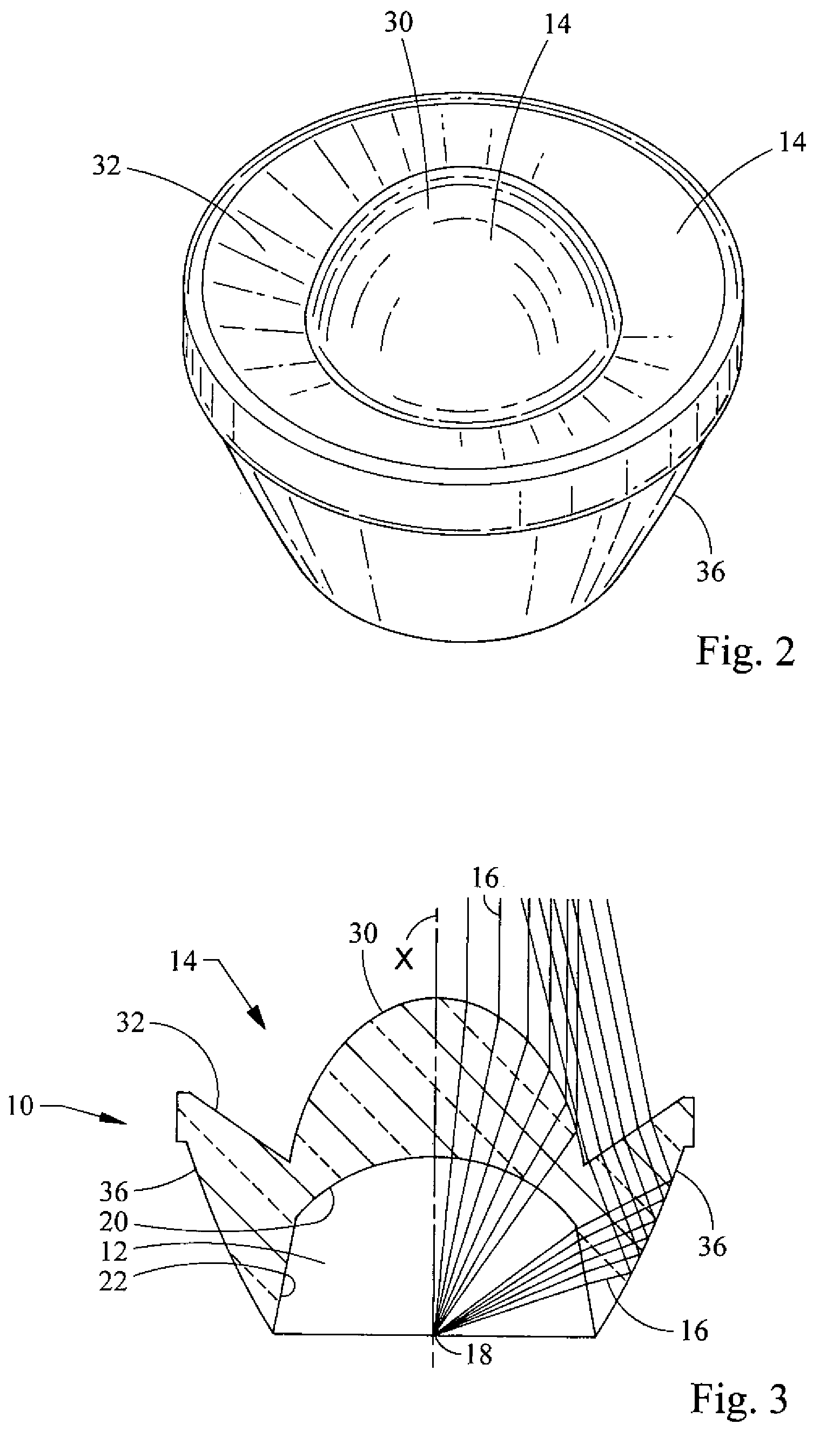
[0018]Referring now to the drawings, a lens embodying the principles of the present invention is illustrated therein and designated at 10. The lens comprises a main body, which is made of a light-transmitting material, preferably, an optical grade plastic, such as polycarbonate or acrylic. The lens 10 may be created by any suitable method, including without limitation, by injection molding. The main body of the lens 10 has a light-collecting face 12 and a light-emitting face 14. An optical axis X extends through the main body of the lens, extending through the centers of the light-collecting face 12 and the light-emitting face 14.

[0019]The light-collecting face 14 defines a pocket in the body of the lens 10 for receiving light 16 from a light source 18, which is illustrated as a light-emitting diode (LED) in this embodiment and hereafter referenced as such. The light source 18 could alternatively be a Lambertian emitter, a 2π emitter, a fiber optic wire guide tip, or any other suita...


PUM


Abstract

A lens for use with a light emitting source is provided. The lens has a main body with a light-collecting face and a light-emitting face and which defines an optical axis extending through the centers of these two faces. A pocket for receiving light from the light source is defined in the light-collecting face by an inner axially-facing surface surrounded by an inner radially-facing surface. The inner axially-facing surface is concave and has a spherical shape. The inner radially-facing surface has a non-spherical, tapered shape and extends between the axially-facing surface and an open end of the pocket. A light assembly incorporating the lens includes a light-emitting diode.

Description

BACKGROUND[0001]1. Field of the Invention[0002]The present invention generally relates to lighting systems involving light pipes, and more particularly, to near field lenses that collect and direct light from light sources and send such light into light pipes.[0003]2. Description of Related Art[0004]Light-emitting diode (LED) light pipes are increasingly finding applications for automotive signal lamps because of their aesthetic look and signature differentiation between vehicle lines. Typical LED light pipes have diameters between five and twenty millimeters with vast variations in length. Styling themes demand light pipes having oddly curved shapes, which are optically challenging to design. This increase in shape complexity of the light pipes makes both the optical design and manufacturing of the light pipe very difficult. Light pipes that have complex shapes typically have lower optical efficiency and require high power LEDs to meet the Federal Motor Vehicle Safety Standards (FM...

Claims


Application Information

Patent Timeline
Patent Type & Authority Patents(United States)
IPC IPC(8): F21V5/00G02B17/00G02B3/02
CPCF21S48/1233G02B19/0061G02B19/0028F21S48/1145F21Y2101/02F21Y2115/10F21S41/14F21S41/28
Inventor CHINNIAH, JEYACHANDRABOSELIN, JEFF C.EICHELBERGER, CHRISTOPHER L.
Owner VARROC LIGHTING SYST SRO
Why Eureka
Try Eureka