Method and apparatus for sequential plasma treatment

a plasma treatment and substrate technology, applied in the direction of decorative arts, chemical vapor deposition coating, catheters, etc., can solve the problems of difficult difficult to achieve plasma treatment of this kind of substrate, and difficulty in creating a uniform plasma density along the substrate length

Inactive Publication Date: 2009-11-17
EURON COMMUNITY EC
View PDF21 Cites 43 Cited by
  • Summary
  • Abstract
  • Description
  • Claims
  • Application Information

AI Technical Summary

Benefits of technology

[0010]In view of such aspects, an object of the present invention is to provide a method and an apparatus in which the above-mentioned problems can be solved. In other

Problems solved by technology

A general difficulty of the use of plasma treatment is the complexity to treat internal walls of such substrates.
Indeed, plasma treatment of this kind of substrate is difficult to perform since the plasma creation into large aspect ratio hollow substrates generally presents a lack of plasma uniformity and thus of treatment.
Two main problems occur when the aim is to treat or to deposit plasma along a hollow substrate.
The first problem concerns the difficulty to create a uniform plasma density along the substrate length.
Indeed, to achieve this condition, a constant electrical energy must be applied to the substrate, which becomes less feasible over a certain size.
The second problem is that uniformity of treatment along the whole length can be ensured only if a constant quantity of precursor reacts all along the substrate length.
Even if a special energy source arrangement can be implemented to create uniform plasma density along the substrate length, the precursor concentration will

Method used


Image

  • Method and apparatus for sequential plasma treatment
  • Method and apparatus for sequential plasma treatment
  • Method and apparatus for sequential plasma treatment

Examples


first embodiment

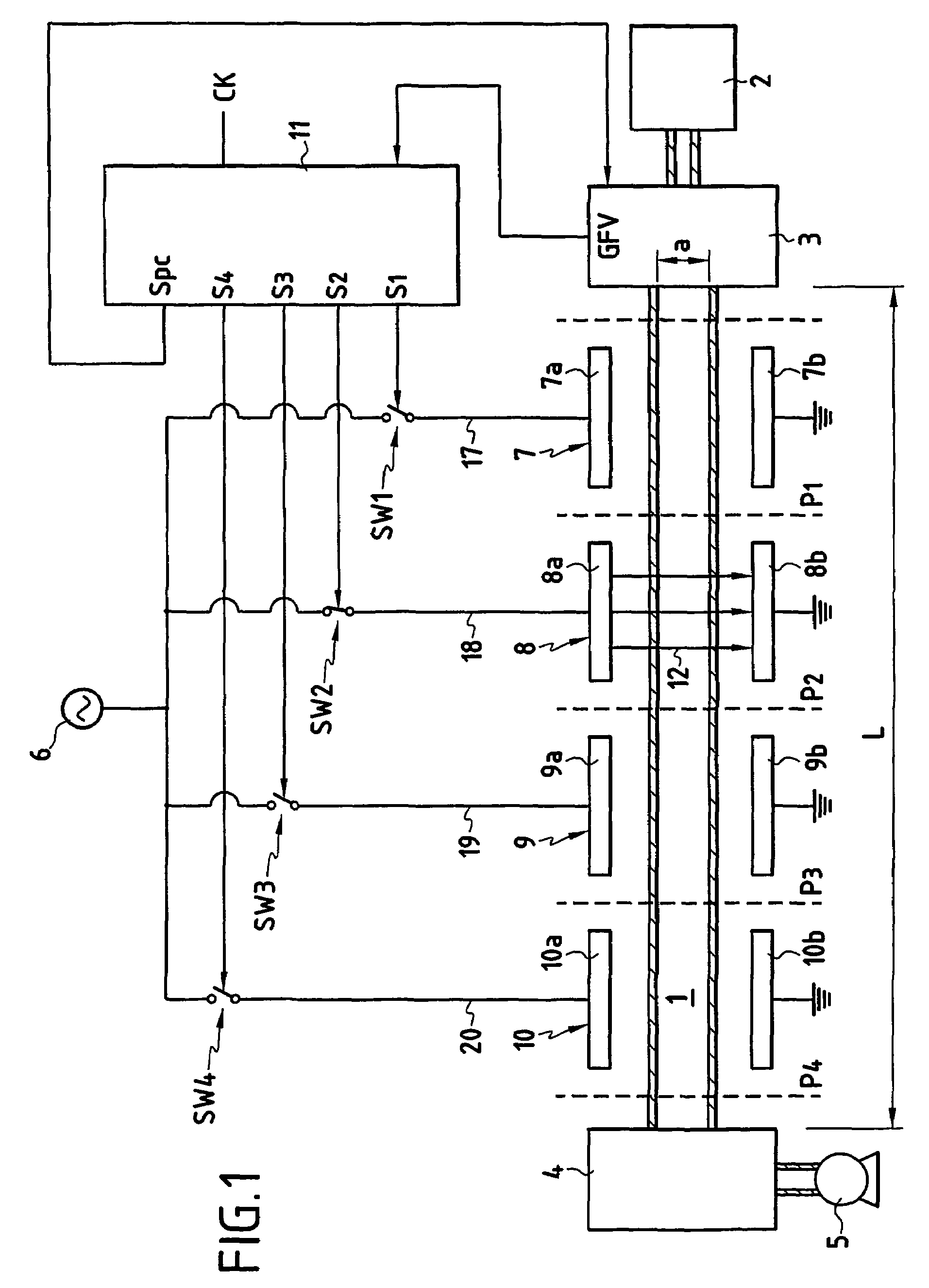
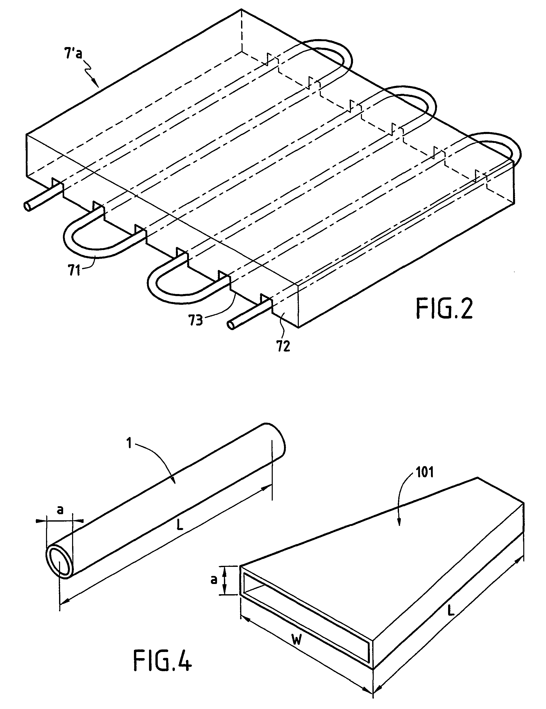
[0036]The method and apparatus for plasma treatment of a non-conductive hollow substrate according to the present invention will be described in relation with a first embodiment illustrated in FIG. 1. A tube 1 having a length L and a diameter a is connected at one extremity to a process gas source 2 through a gas flow controller 3. The process gas supplied from the source 2 contains a precursor, such as acrylic acid, in order to create plasma. The quantity of precursor supplied to the internal cavity of the tube is controlled by the gas flow controller 3 which sets the kinetic of the gas injected in the tube. The opposite extremity of the tube 1 is in communication with a device 4 connected to a vacuum pump 5.

[0037]Four ionisation energy sources 7 to 10 are disposed adjacent to each other along the substrate length L. The ionisation energy sources, which will be referred hereinafter as plasma sources, each comprises a first and second electrodes 7a, 7b (respectively 8a, 8b; 9a, 9b; ...

second embodiment

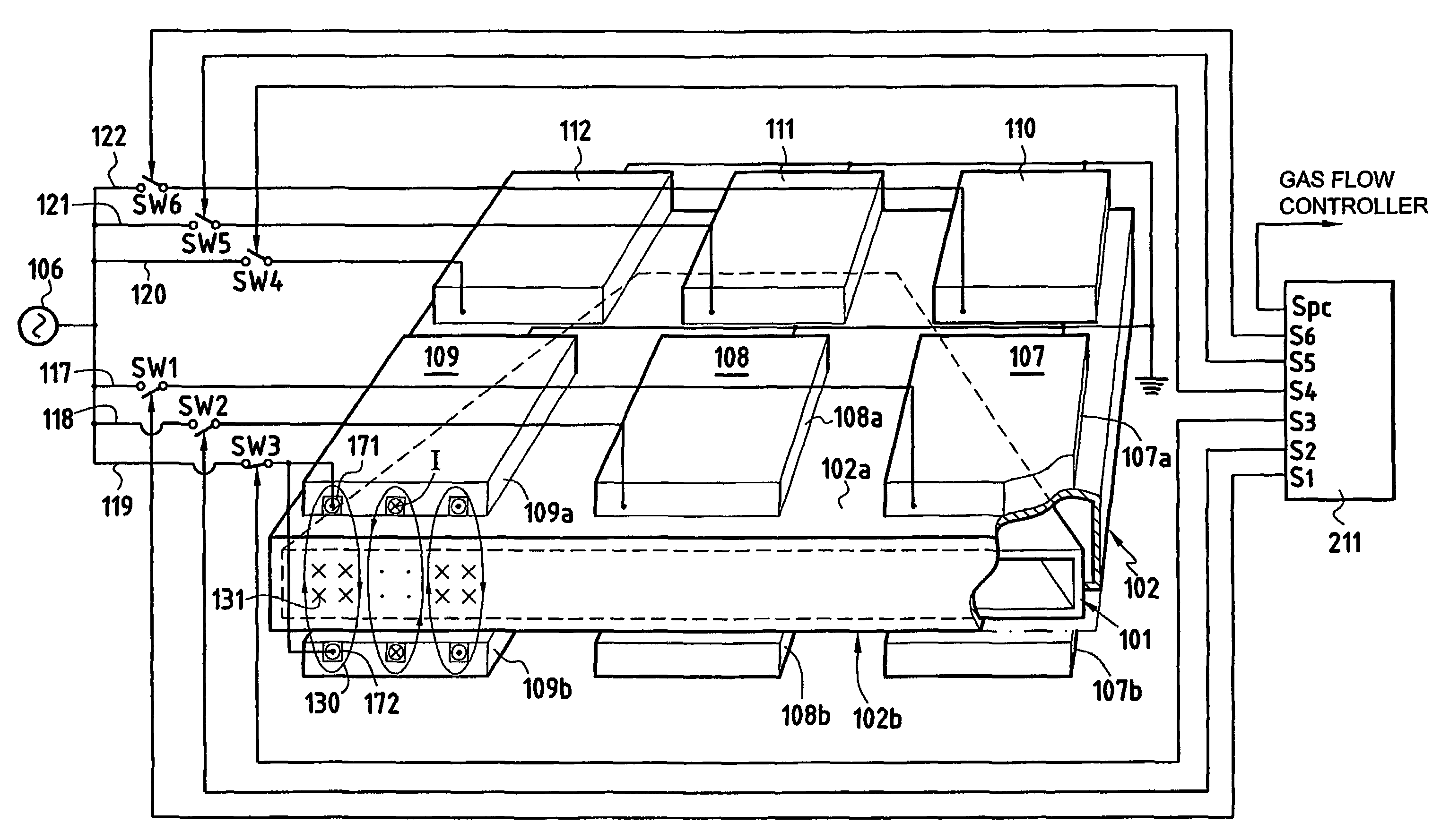
[0060]FIG. 3 illustrates an apparatus for plasma treatment according to the present invention. In this embodiment, the set of plasma sources is comprised of an array of six plasma sources 107 to 112 disposed according two directions. Indeed, the substrate to be treated is a flat box 101 as that represented in FIG. 4. As can be seen from FIG. 3, three plasma sources 107 to 109 are disposed adjacent to each other according to a first row while the sources 110 to 112 are respectively aligned with the sources 107 to 109 according to a second row. The disposition of the plasma sources 107 to 112 according to an array of two dimensions matches the form of the flat box 101 which, contrary to a tube, presents a width W shown in FIG. 4.

[0061]As shown for the plasma source 107, each source comprises two parts 107a and 107b sandwiching the flat box 101 to be treated. The two parts of each source may be reactance electrodes or, as represented in FIG. 3, two coils arrangements having the structu...


PUM

PropertyMeasurementUnit
Fractionaaaaaaaaaa
Frequencyaaaaaaaaaa
Frequencyaaaaaaaaaa

Abstract

An apparatus for plasma treatment of a non-conductive hollow substrate, including a plurality of ionization energy sources disposed adjacent to each other all along the part of the substrate to be treated. The apparatus also includes a processor to sequentially power the plurality of ionization energy sources from a radio frequency power source. Each ionization energy source includes two parts sandwiching the substrate. The ionization energy sources can be capacitively or inductively coupled plasma sources.

Description

FIELD OF THE INVENTION[0001]The present invention relates to a method and an apparatus for substrate treatments using plasma such as, for example, polymer treatment for biomedical devices or food and pharmaceutical packaging devices. In particular, the present invention relates to plasma treatment or deposition in non conductive hollow substrates having large aspect ratio such as small diameter tubes, flat boxes.BACKGROUND OF THE INVENTION[0002]Hollow substrates with a large aspect ratio are commonly used in various technological fields such as catheters or endoscopes for medical materials and packaging for food or pharmaceutical applications. The expression “large aspect ratio” means that the hollow substrate has at least one dimension that is much larger than another one, and more particularly that the length of the substrate is much larger than a dimension of the substrate aperture. FIG. 4 shows two examples of hollow substrates which have a large aspect ratio L / a, where L is the...

Claims


Application Information

Patent Timeline
IPC IPC(8): H05H1/46B05D3/06C23C16/505C23C16/507C23C16/515C23C16/52H05H1/24A61J1/10A61M25/00B01J19/08H01J37/32
CPCC23C16/515H01J37/32394H01J37/321H01J37/32091H01L21/02
Inventor COLPO, PASCALROSSI, FRANCOIS
Owner EURON COMMUNITY EC
Why Eureka
Try Eureka