
Apparatus and method for calibration of gain and/or phase imbalance and/or DC offset in a communication system

a communication system and gain and phase imbalance technology, applied in the field of error correction, can solve the problems of increasing bandwidth, reducing the reliability of transceivers, and reducing the reliability of receivers, and achieving the effect of efficient and cost-effective apparatus

Inactive Publication Date: 2009-11-17
SIERRA MONOLITHICS INC
View PDF12 Cites 54 Cited by
  • Summary
  • Abstract
  • Description
  • Claims
  • Application Information

AI Technical Summary

Benefits of technology

"The present invention provides an efficient and cost-effective apparatus and method for off-line calibration of communication systems. It includes a transmit pre-distortion module and a receive channel frequency converter with a calibration module that can calibrate the transmit and receive channels separately. The calibration signals are generated using a calibration signal generator and filters to separate and provide the calibration error signals. The system also includes a multiplexer to select between the calibration signals and the communication signals. The calibration error signals are caused by gain and phase imbalance, as well as DC offset. The invention allows for accurate and efficient calibration of communication systems without affecting the communication signal."

Problems solved by technology

Telecommunication standards such as the IEEE 802.16 Standard for broadband wireless access (BWA) has imposed clear and often challenging requirements on the radio portion of the communication systems.
This increase in bandwidth comes with little relief for the transceiver fidelity requirements.
All of this comes with no relief in the worldwide regulatory requirements on emissions and receiver robustness.

Method used


Image

  • Apparatus and method for calibration of gain and/or phase imbalance and/or DC offset in a communication system
  • Apparatus and method for calibration of gain and/or phase imbalance and/or DC offset in a communication system
  • Apparatus and method for calibration of gain and/or phase imbalance and/or DC offset in a communication system

Examples


Embodiment Construction

[0097]In the following detailed description, numerous specific details are set forth to provide a full understanding of the present invention. It will be obvious, however, to one ordinarily skilled in the art that the present invention may be practiced without some of these specific details. In other instances, well-known structures and techniques have not been shown in detail not to obscure the present invention.

[0098]Introduction

[0099]Transceiver systems and off-line calibration procedures for transceiver systems are described in accordance with one embodiment of the present invention. According to one embodiment, these procedures involve the participation of a baseband subsystem or device. The overall calibration strategy and the technique to be applied may require operation of a radio frequency (RF) subsystem and a baseband subsystem. The procedures herein described make as few assumptions as possible about the baseband device to accommodate a variety of such devices. For any gi...


PUM


Abstract

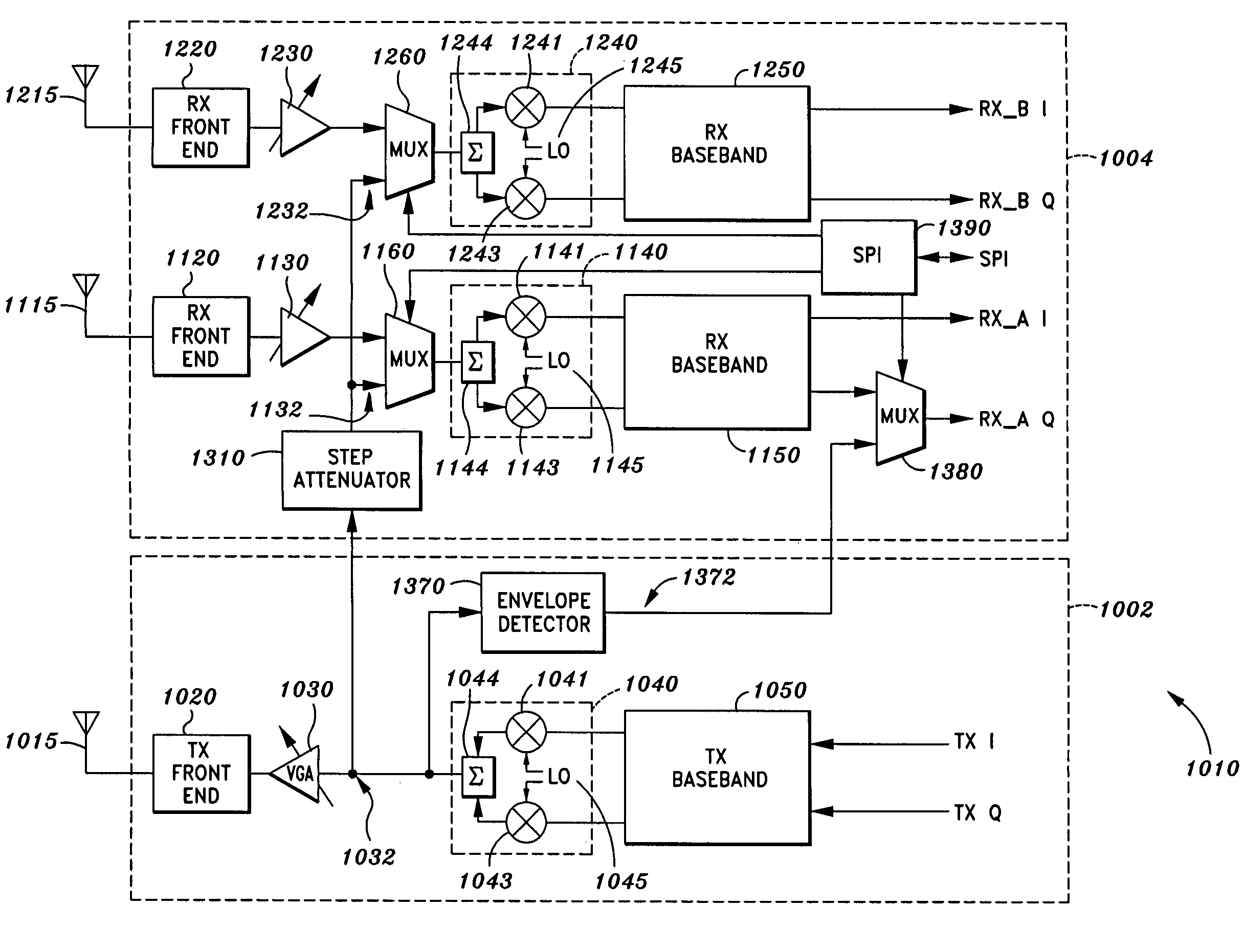
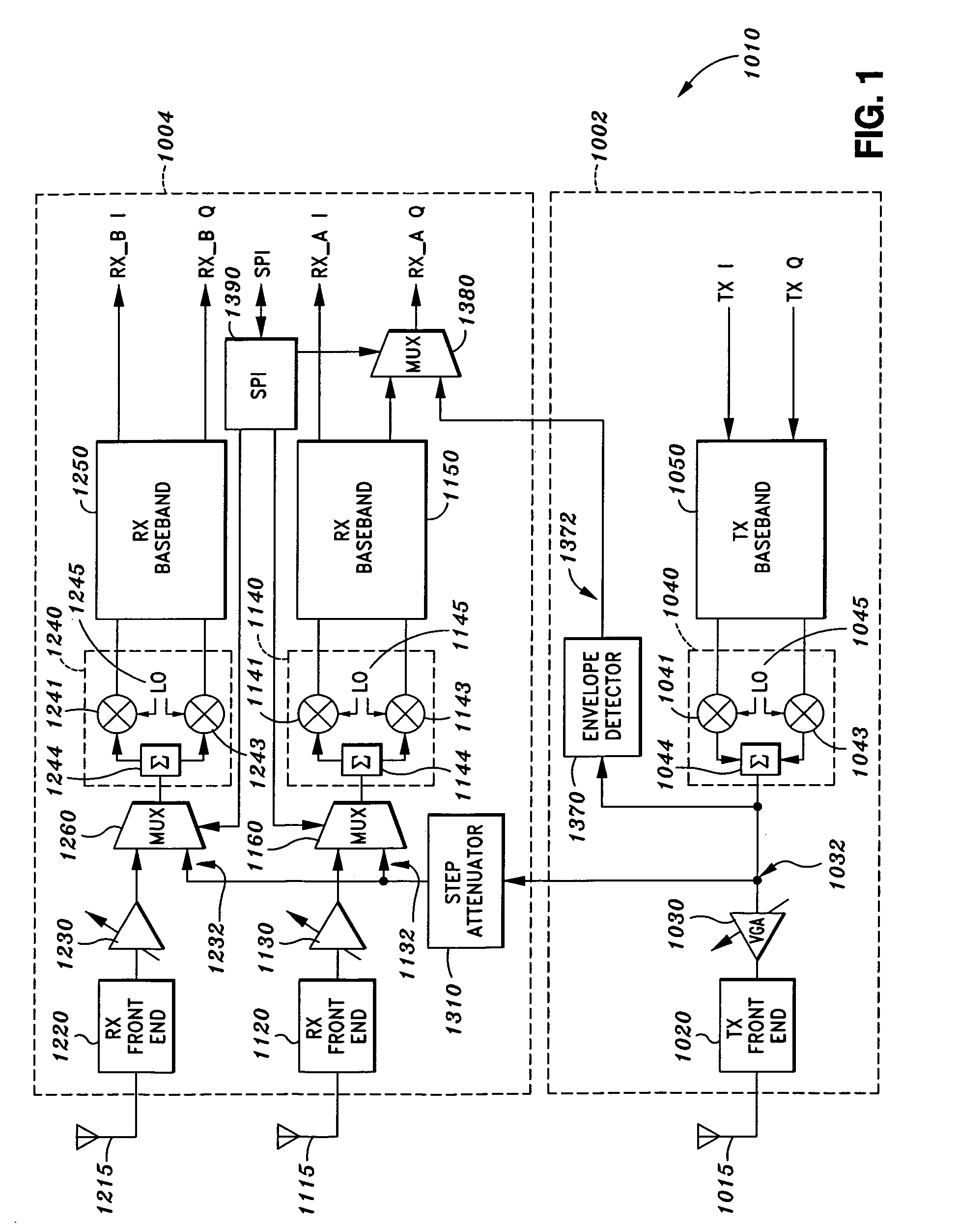
A radio frequency transceiver for off-line transmit and receive calibrations includes: a transmit pre-distortion module configured to receive a transmit calibration signal during a transmit calibration mode, a transmit communication signal during a transmit communication operation mode, and one or more transmit calibration adjustment signals; a transmit channel frequency converter; and a transmit calibration module configured to provide the one or more transmit calibration adjustment signals and the transmit calibration signal to the transmit pre-distortion module. It may also include a receive channel frequency converter; a receive pre-distortion module configured to receive a receive calibration signal during the receive calibration mode, a receive communication signal during a receive communication operation mode, and one or more receive calibration adjustment signals; and a receive calibration module configured to provide the one or more receive calibration adjustment signals to the receive pre-distortion module and a receive calibration signal to the transmit pre-distortion module.

Description

CROSS-REFERENCES TO RELATED APPLICATIONS[0001]The present application claims the benefit of priority under 35 U.S.C. §119 from U.S. Provisional Patent Application Ser. No. 60 / 816,240 entitled “CALIBRATION OR CORRECTION OF QUADRATURE ERRORS AND / OR DC OFFSET ERRORS IN A TRANSMITTER AND / OR RECEIVER,” filed on Jun. 23, 2006, which is hereby incorporated by reference in its entirety for all purposes.FIELD OF THE INVENTION[0002]The present invention generally relates to error correction and, in particular, relates to apparatus and methods for off-line calibration of gain and phase imbalance and DC offset in a communication system.BACKGROUND OF THE INVENTION[0003]Telecommunication standards such as the IEEE 802.16 Standard for broadband wireless access (BWA) has imposed clear and often challenging requirements on the radio portion of the communication systems. The most recent revisions have increased channel bandwidth through scalable addition of sub-carriers for the orthogonal frequency d...

Claims


Application Information

Patent Timeline
Patent Type & Authority Patents(United States)
IPC IPC(8): H04B1/38
CPCH04B17/14H04B17/104H04B17/101H04B7/08
Inventor COLE, JEAN-PIERRE JOSEPHROWE, DAVID A.HORNBUCKLE, CRAIG A.
Owner SIERRA MONOLITHICS INC
Learn More