[0010]In a preferred embodiment of the invention, the radial expansion of the spacer is utilized to achieve a high intra-vertebral fill, without an overly invasive surgical procedure. Preferably, a high contact surface between the spacer and the vertebrae is achieved.
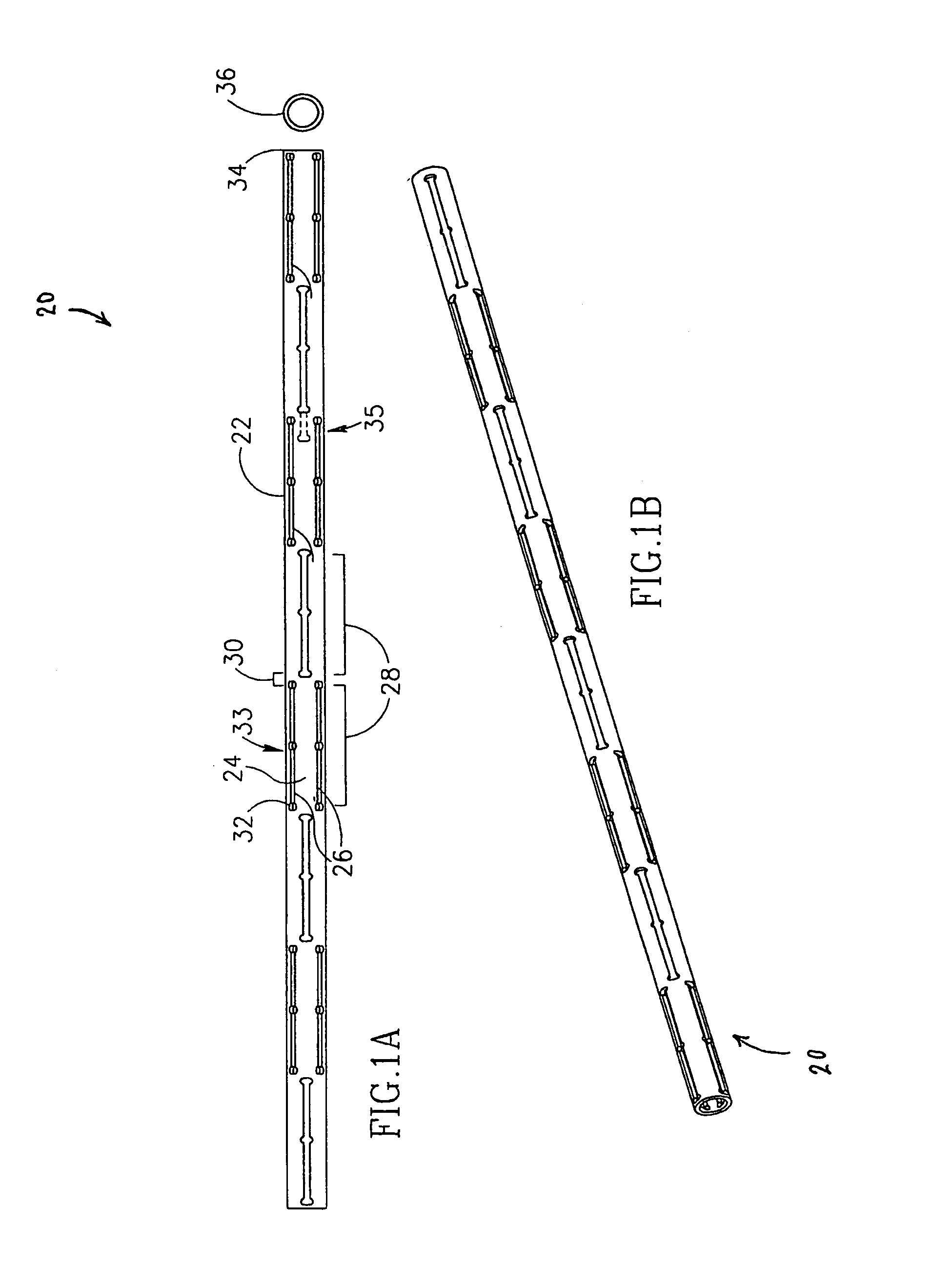
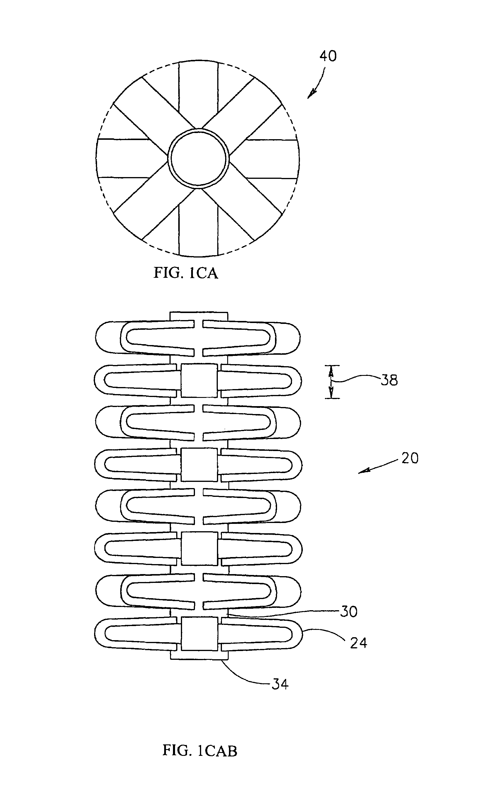
[0014]A finished spacer, in accordance with some preferred embodiments of the invention, comprises a plurality of spikes that are provided into the body to provide a desired geometrical shape, for example to space apart two vertebrae. The tube body parts that do not expand, serve to interconnect the spikes, for example to prevent them from getting lost and / or for aiding in or performing guiding the final placement of the spikes, so that the desired final geometry is achieved. Thus, geometric constructs other than spikes may also be provided to a same effect.
[0023]An aspect of some preferred embodiments of the invention relates to forming the tube of a material having an uneven thickness and / or mechanical properties. In some embodiments, mechanical characteristics of a spacer are modified after the spacer (or a tube from which it is
cut) is constructed. In other embodiments, such mechanical characteristics may be at least partly modified before the spacer is formed. In a preferred embodiment of the invention,
increased thickness and / or strength is provided at points or areas where stress is concentrated when pressure is applied to the spikes in an expanded spacer. Alternatively or additionally,
increased thickness and / or strength is provided at points where stress is concentrated when pressure is applied to the spikes in an expanded spacer. Alternatively or additionally,
increased thickness and / or one or more protrusions are provided on one or more spikes to mechanically block a collapsing of the spikes after the tube is expanded. In one example, when the spacer comprises alternating segments of spikes, a segment may include one or more protrusions which strengthen the spikes on an
adjacent segment. Alternatively or additionally, a lower strength and / or pre-stressing is applied to portions of the tube which are expected to fold (and / or stretch) when the tube is expanded. Alternatively or additionally, variations in thickness and / or strength and / or elasticity define portions of the spacer which better conform to surrounding tissue. In some embodiments of the invention, the spacer matches the geometry of the surrounding tissue. In other embodiments, the mechanical characteristics of the spacer are matched to the surrounding tissue, for example providing more give where the spacer is against a hard bone.
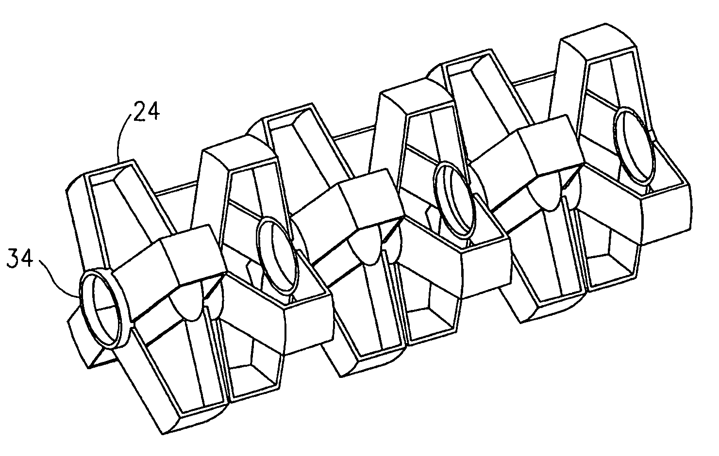
[0024]An aspect of some preferred embodiments of the invention relates to a inter-vertebral spacer having extending spikes, in which at least some of the spikes have a non-V shaped profile. In a preferred embodiment of the invention, the spikes have a flat top, possibly with small protrusions formed thereon, so that the spikes do not dig into the vertebrae. Alternatively or additionally, the spikes have concave sides, so that when are stressed, they do not collapse.
[0037]Alternatively or additionally to using struts, one or more of these strut-functions may be provided by wires. As used herein the differences between wires and struts (both of which are examples of inter-connecting elements), are mainly in their relative rigidity and thicknesses. Additionally, struts usually maintain the same rigid configuration when the spacer is expanded and when it is collapsed (or folded at pre-defined points), while wires may change their configuration, for example being folded when the spacer is collapsed and being extended when the spacer is expanded. Alternatively or additionally to directly structural functions, the struts and / or wires may be used to effect a desired contact surface, for example, to enhance fusion with bone or to limit embedding or sinking of spikes in the surrounding bone.
[0091]In a preferred embodiment of the invention, the spacer comprises at least protrusion on at least on of said extensions, to prevent collapsing of said extension.

