Method for shielding the magnetic field generated by an electrical power transmission line and electrical power transmission line so shielded

a technology of electrical power transmission line and shielding magnetic field, which is applied in the direction of electrically conductive connections, conductors, electrical apparatus, etc., can solve the problems of affecting the overall weight of the transmission line, the cost of the line and maintenance, and the disadvantages of shielding, so as to achieve effective mitigation of the magnetic field and facilitate installation

Inactive Publication Date: 2009-11-24
PRYSMIAN CAVI E SISTEMI ENERGIA
View PDF15 Cites 13 Cited by
  • Summary
  • Abstract
  • Description
  • Claims
  • Application Information

AI Technical Summary

Benefits of technology

[0023]The Applicant has found that it is possible to manufacture an electrical power transmission line which is easy to be installed by providing a shielding element comprising two components, in particular a base and a cover, while obtaining an effective mitigatio...

Problems solved by technology

These shields have a number of disadvantages which have not been overcome yet.
Firstly, such shields need to be sensibly thick (1-10 mm) in order to provide a sufficiently effective shielding action, with negative consequences on the total weight of the transmission line, on the simplicity and on the rapidity of the installation and maintenance operations and, last but not least, on the cost of the line and of the maintenance thereof.
Secondly, although the closed-section conduits described above provide the best shielding effects of the magnetic field, the Applicant noted that the installation and maintenance of the cables into closed conduits is a difficult and costly operation since the cables need to be inserted into the conduits and, in case of maintenance, the cables cannot be inspected because they are surrounded by the conduit.
Thirdly, the prior art shields, whether open-section or closed-section shields, are subject to unacceptable electrical losses (i.e. due to eddy currents) and/or hysteretic losses.
In order to ensure an effective magnetic field shielding action, the thickness of the shield is quite high (in the order of 10 mm), which implies an increase of the weight of the transmission line and an ensuing increased difficulty in cable laying operations, which are already quite difficult due to the closed geometry of the conduit.
Also in this case, the closed section of the conduit makes the cable laying operations complicated.
Although substantially achieving the pu...

Method used


Image

  • Method for shielding the magnetic field generated by an electrical power transmission line and electrical power transmission line so shielded
  • Method for shielding the magnetic field generated by an electrical power transmission line and electrical power transmission line so shielded
  • Method for shielding the magnetic field generated by an electrical power transmission line and electrical power transmission line so shielded

Examples


example 1

Invention

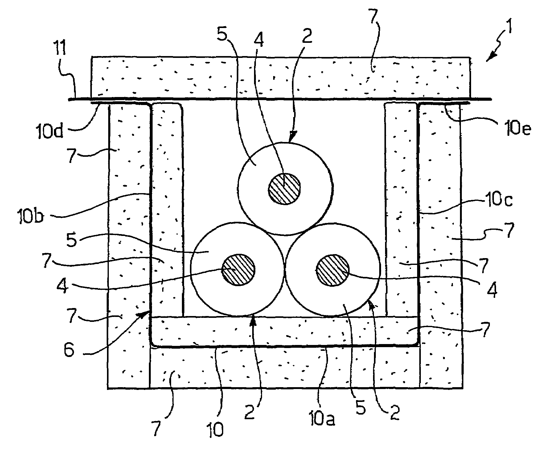
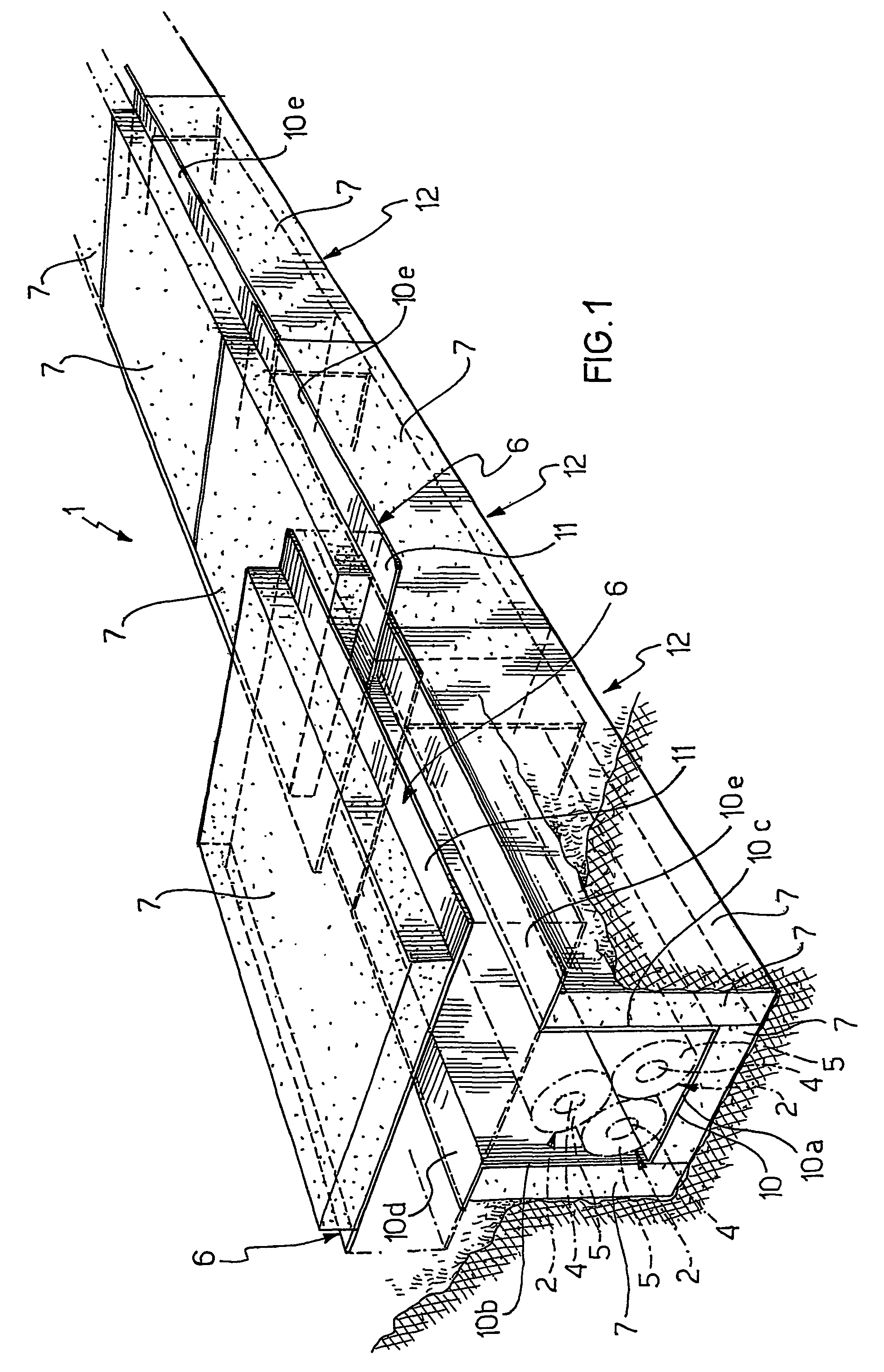
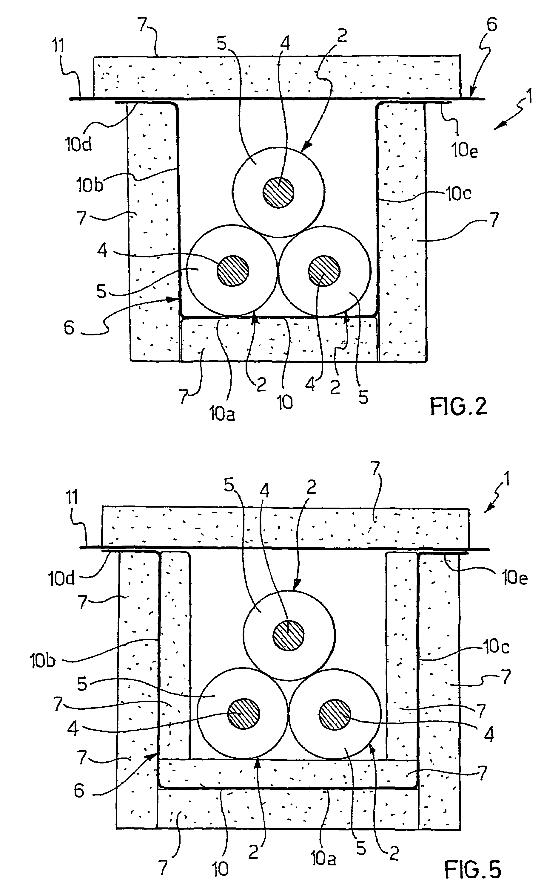
[0191]The Applicant manufactured an electrical power transmission line comprising three 150 kV electrical cables, having a section equal to about 1000 mm2 and a diameter equal to about 92 mm, arranged according to a trefoil arrangement of the closed type, and a shielding element comprising 5 modules, each of said modules comprising a modular base and a modular cover.

[0192]The shielding element was made of grain oriented silicon steel starting from a strip having a width of 470 mm and a thickness of 0.27 mm

[0193]In particular, the steel referred to as M4T27 according to the AST standard was used. For each module, a steel strip was cut into rectangular sheets (460 mm×690 mm) and subsequently folded by means of a manual bending apparatus to form a modular base comprising a 190 mm wide substantially flat bottom wall, a pair of substantially flat side walls (200 mm long) extending in a direction substantially perpendicular to the bottom wall, and a pair of substantially flat fla...

example 2

Comparison

[0209]A non-shielded electrical power transmission line comprising three electrical cables arranged according to a trefoil arrangement, laid in a trench at a depth of 1.4 metres, having the same constructive characteristics and subject to the same working conditions of the cables of the shielded line described in Example 1 was manufactured.

example 3

Invention

[0210]An electrical power transmission line as described in Example 1, except for the fact that the covers were arranged with the axis of the grains oriented in the direction parallel to the cable axis, was manufactured.


PUM


Abstract

A method for shielding the magnetic field generated by an electrical power transmission line and an electrical power transmission line so shielded. The electrical power transmission line has at least one electrical cable and at least one shielding element made of ferromagnetic material arranged in a radially outer position with respect to the at least one cable which shielding element has a base and a cover. The line also has a supporting element coupled to at least the base of the shielding element. In particular, the ferromagnetic material of the shielding element is selected from grain oriented silicon steel, preferably containing a silicon content between about 1% and about 5%, non-grain oriented silicon steel, Permalloyè and Supermalloyè.

Description

CROSS REFERENCE TO RELATED APPLICATION[0001]This application is a national phase application based on PCT / IT2003 / 000476, filed Jul. 30, 2003, the content of which is incorporated herein by reference.FIELD OF THE INVENTION[0002]The present invention relates to a method for shielding the magnetic field generated by an electrical power transmission line and to an electrical power transmission line so shielded.DESCRIPTION OF THE RELATED ART[0003]Generally, an electrical power transmission line operates at medium voltage (typically from 10 to 60 kV) or at high voltage (typically greater than 60 kV) and at currents of the order of hundreds-thousands of amperes (typically from 500 to 2000 A). The electrical power carried by these lines can reach values of the order of hundreds of MVA, typically 400 MVA. Normally, the carried current is an alternating current at low frequency, in other words generally below 400 Hz and typically equal to 50 or 60 Hz. In general, the electrical power transmis...

Claims


Application Information

Patent Timeline
IPC IPC(8): H01B11/06H02G9/04H02G9/06
CPCH02G9/065H02G9/04
Inventor DONAZZI, FABRIZIOBELLI, SERGIOMAIOLI, PAOLOBORGHI, ENRICO
Owner PRYSMIAN CAVI E SISTEMI ENERGIA
Why Eureka
Try Eureka