Method and system for controlling permanent magnet AC machines

a technology of alternating current and control method, which is applied in the direction of motor/generator/converter stopper, dynamo-electric converter control, starter details, etc., can solve the problems of weak flux pm machine field-weakened operation, insufficient d-axis current control, and limited success of d-axis current control techniques

Active Publication Date: 2009-11-24
GM GLOBAL TECH OPERATIONS LLC
View PDF18 Cites 16 Cited by
  • Summary
  • Abstract
  • Description
  • Claims
  • Application Information

AI Technical Summary

Problems solved by technology

These d-axis current control techniques have limited success with weak flux PM machines due to the weak influence of the d-axis current on the machine voltage.
For example, in the non-linear overmodulation region of operation, the low influence of the d-axis current on the total machine flux may impair field-weakened operation of a weak flux PM machine.
In this case, increasing the negative d-axis current can cause instability by increasing the total voltage magnitude instead of decreasing the same.
Hence, d-axis current control may be inadequate for some PM machines that operate at a high velocity with a large demagnetizing current.
Due to the presence of non-idealities, such as parameter variation (e.g., manufacturing tolerances, temperature, aging, etc.), the stator voltage tends to deviate from the desired value.

Method used


Image

  • Method and system for controlling permanent magnet AC machines
  • Method and system for controlling permanent magnet AC machines
  • Method and system for controlling permanent magnet AC machines

Examples


Embodiment Construction

[0019]The following detailed description is merely illustrative in nature and is not intended to limit the invention or the application and uses of the invention. Furthermore, there is no intention to be bound by any expressed or implied theory presented in the preceding technical field, background, brief summary or the following detailed description.

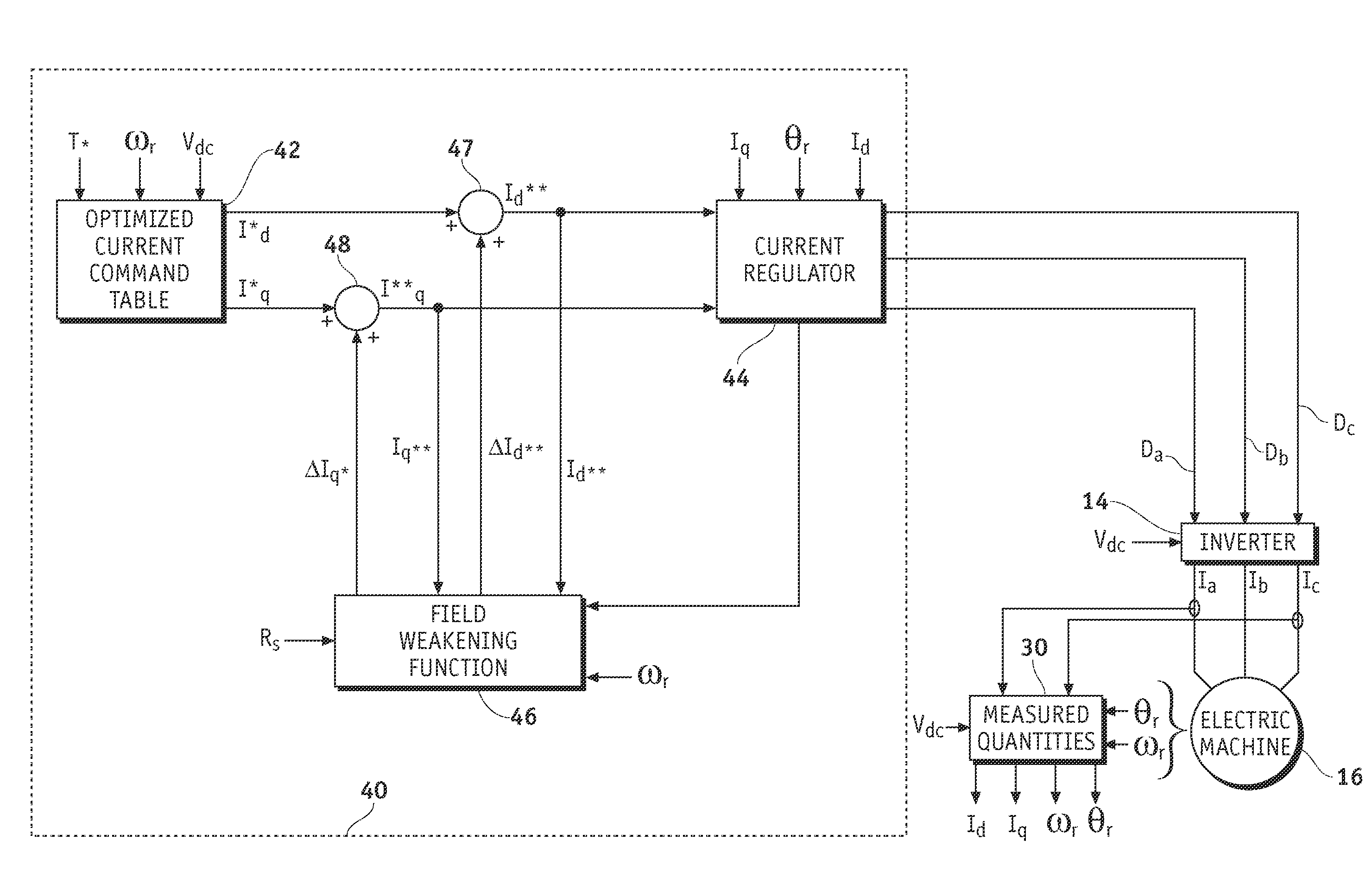
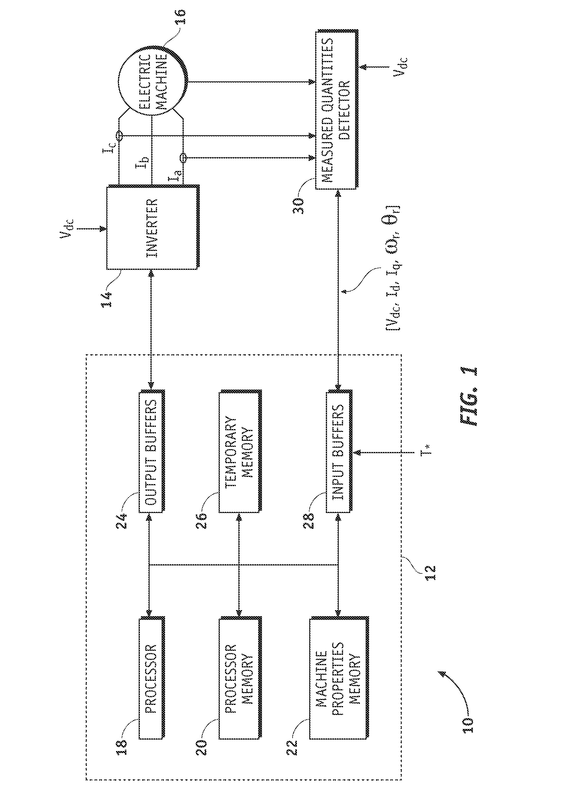
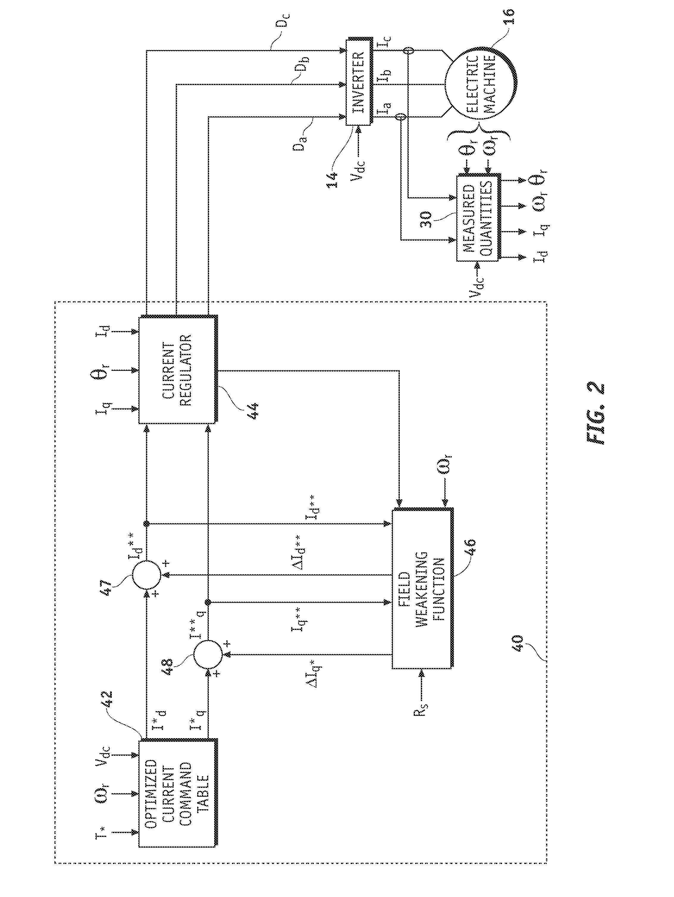
[0020]A system and method are provided for controlling a permanent magnet (PM) machine. In general, the system comprises a current control system having a feedback loop providing regulation of a stator voltage for light load or no load operating conditions of the PM machine. In an exemplary embodiment, the current control system comprises a current command source, a current regulator coupled to the current command source, and a field-weakening voltage control module coupled between an output and an input of the current regulator. The current regulator produces d- and q-axis voltage commands based on d- and q-axis current commands, as we...


PUM


Abstract

Methods and systems are provided for controlling permanent magnet machines under varying loads. The method comprises generating a d-axis voltage command and a q-axis voltage command, producing a modified d-axis current command based on the q-axis voltage command and a d-axis current command, converting the modified d-axis current command to a modified d-axis voltage command, and transmitting the modified d-axis voltage command and the q-axis voltage command to the PM machine. The d-axis voltage command is based on a d-axis current command.

Description

TECHNICAL FIELD[0001]The present invention generally relates to controlling alternating current (AC) machines, and more particularly relates to systems and methods for controlling permanent magnet machines.BACKGROUND OF THE INVENTION[0002]In permanent magnet (PM) type machines, the presence of the magnet generates a magnetic flux, even when lacking a stator current. This flux typically results in a back electromotive force (EMF) that is proportional to the motor speed and that may increase beyond a direct current (DC) bus voltage. For example, the phase voltage of a PM machine increases as the velocity of the machine is increased. Above a predetermined velocity, the peak line-to-line voltage of the PM machine becomes greater than the bus voltage. To retain current control of the PM machine, the back EMF is generally reduced using field-weakening. A variety of field-weakening techniques are available, and the selection of a particular field-weakening technique may be based on the cha...

Claims


Application Information

Patent Timeline
Patent Type & Authority Patents(United States)
IPC IPC(8): H02P7/00
CPCH02P21/0089H02P21/05H02P21/02
Inventor SCHULZ, STEVEN E.HITI, SILVARAHMAN, KHWAJA M.
Owner GM GLOBAL TECH OPERATIONS LLC
Why Eureka
Try Eureka