Bias circuit with increased power supply rejection

a bias circuit and power supply technology, applied in the field of electric circuits, can solve the problems of poor power supply rejection of conventional bias circuits, undesirable affecting microphone performance, etc., and achieve the effect of increasing power supply rejection

Inactive Publication Date: 2009-11-24
AVAGO TECH INT SALES PTE LTD
View PDF4 Cites 25 Cited by
  • Summary
  • Abstract
  • Description
  • Claims
  • Application Information

AI Technical Summary

Problems solved by technology

Furthermore, the bias voltage needs to have low noise to ensure sufficient audio quality and should be very insensitive to any variation on the power supply to maintain a stable voltage across the microphone.
However, in the conventional bias circuit, noise on the transistor's supply voltage (e.g. VDD) can easily be coupled to the output of the bias circuit, thereby undesirably affecting microphone performance.
Thus, the conventional bias circuit typically exhibits poor power supply rejection (PSR), which refers to the capability of the bias circuit to reject variations in supply voltage caused by noise.

Method used


Image

  • Bias circuit with increased power supply rejection
  • Bias circuit with increased power supply rejection
  • Bias circuit with increased power supply rejection

Examples


Embodiment Construction

[0011]The present invention is directed to a bias circuit with increased power supply rejection. The following description contains specific information pertaining to the implementation of the present invention. One skilled in the art will recognize that the present invention may be implemented in a manner different from that specifically discussed in the present application. Moreover, some of the specific details of the invention are not discussed in order not to obscure the invention.

[0012]The drawings in the present application and their accompanying detailed description are directed to merely exemplary embodiments of the invention. To maintain brevity, other embodiments of the present invention are not specifically described in the present application and are not specifically illustrated by the present drawings.

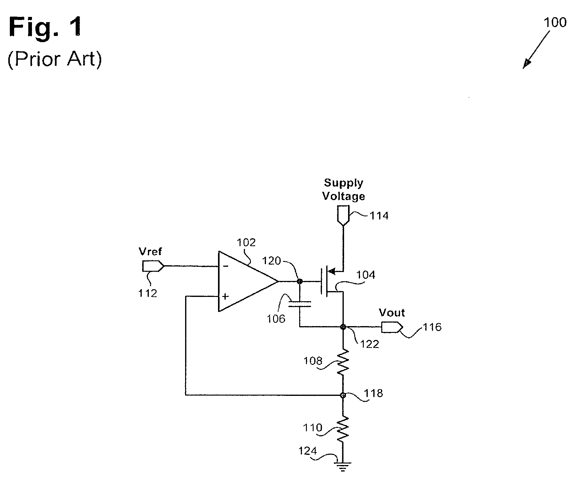
[0013]FIG. 1 shows a circuit diagram of an exemplary conventional bias circuit. Conventional bias circuit 100 includes amplifier 102, output transistor 104, capacitor 106...


PUM


Abstract

According to one exemplary embodiment, a power supply rejection bias circuit includes a first amplifier coupled to a second amplifier, where the first amplifier receives a reference voltage, and a feedback voltage of the bias circuit. The bias circuit further includes an output transistor driven by the output of the second amplifier, where the output transistor provides the output of the bias circuit and the feedback voltage. The bias circuit further includes a feedback resistor coupled between an input and an output of the second amplifier. According to this embodiment, the output of the second amplifier forms a non-dominant pole of the bias circuit and the output of the bias circuit forms a dominant pole of the bias circuit, thereby increasing power supply rejection of the bias circuit.

Description

BACKGROUND OF THE INVENTION[0001]1. Field of the Invention[0002]The present invention is generally in the field of electrical circuits. More particularly, the invention is in the field of bias circuits.[0003]2. Background Art[0004]Microphones, such as microphones used in cell phones, computers, and handheld audio devices, typically require a stable bias voltage to operate. For proper microphone operation, the bias voltage needs to remain at a constant level that is independent of the load current, i.e. the amount of current that flows into the microphone. Furthermore, the bias voltage needs to have low noise to ensure sufficient audio quality and should be very insensitive to any variation on the power supply to maintain a stable voltage across the microphone.[0005]A conventional bias circuit for providing a microphone bias voltage can include a high impedance operational amplifier coupled to a transistor, such as a PMOS transistor. The conventional bias circuit can also include a f...

Claims


Application Information

Patent Timeline
Patent Type & Authority Patents(United States)
IPC IPC(8): H03F1/30
CPCH03F1/301
Inventor GALAL, SHERIF
Owner AVAGO TECH INT SALES PTE LTD
Why Eureka
Try Eureka