

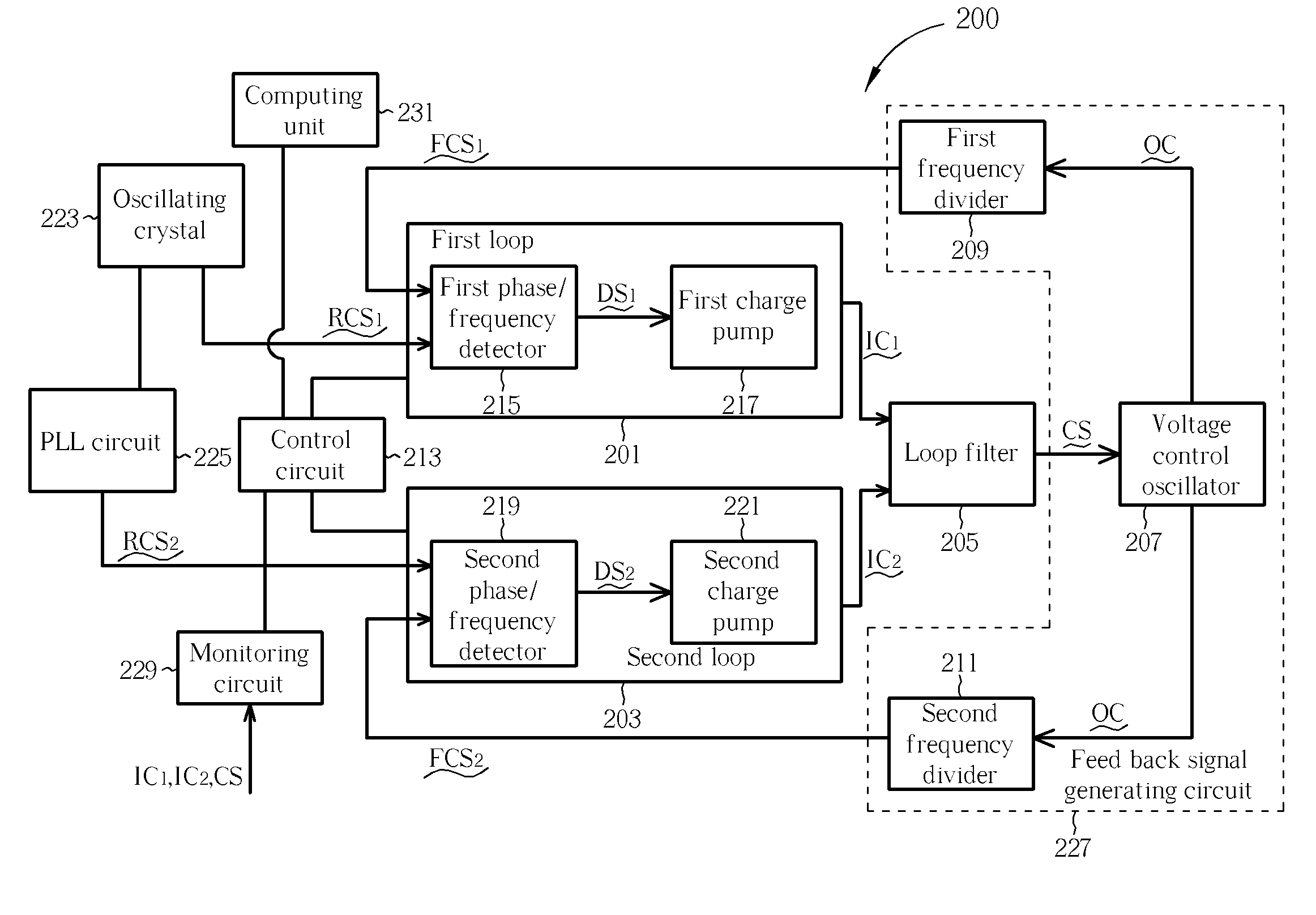
Multi-loop phase locked loop circuit
a phase locking loop and loop circuit technology, applied in the direction of electrical equipment, pulse automatic control, etc., can solve the problems of limited speed of the above-mentioned prior art pll and the inability to meet the demand of high frequency jumping systems such as uwb (ultra wideband), so as to reduce the lock time of the pll
- Summary
- Abstract
- Description
- Claims
- Application Information
AI Technical Summary
Benefits of technology
Problems solved by technology
Method used
Image


Examples
Embodiment Construction
[0018]Certain terms are used throughout the description and following claims to refer to particular components. As one skilled in the art will appreciate, electronic equipment manufacturers may refer to a component by different names. This document does not intend to distinguish between components that differ in name but not function. In the following description and in the claims, the terms “include” and “comprise” are used in an open-ended fashion, and thus should be interpreted to mean “include, but not limited to . . ..”. Also, the term “couple” is intended to mean either an indirect or direct electrical connection. Accordingly, if one device is coupled to another device, that connection may be through a direct electrical connection, or through an indirect electrical connection via other devices and connections.
[0019]It should be noted that the embodiment according to the present invention described below can be used in UWB, but this is not meant to limit the scope of the presen...
PUM
 Abstract
Description
Claims
Application Information