
Device including piezoelectric thin film and a support having a vertical cross-section with a curvature

a piezoelectric thin film and vertical cross-section technology, applied in the field of piezoelectric thin film devices, can solve the problems of unnecessary vibration, spurious frequency characteristics, and need to be redesigned, so as to prevent unnecessary vibration, suppress spurious, and avoid the effect of reducing reliability

Inactive Publication Date: 2009-11-24
PANASONIC CORP
View PDF20 Cites 14 Cited by
  • Summary
  • Abstract
  • Description
  • Claims
  • Application Information

AI Technical Summary

Benefits of technology

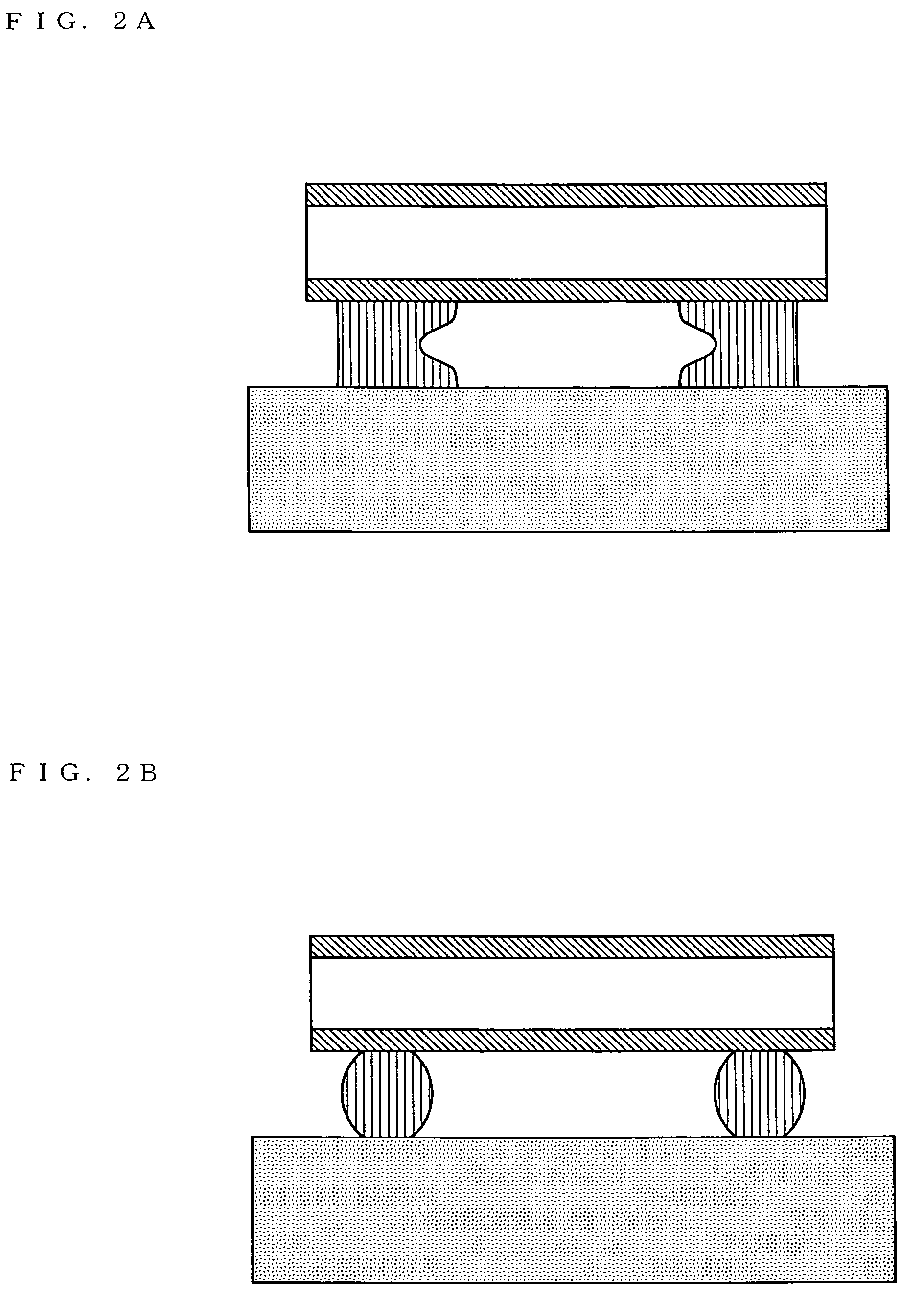
"The present invention provides a device that includes a piezoelectric thin film and is capable of preventing generation of unnecessary vibrations and reducing stress concentration. The device includes an acoustic resonator and a micromachine switch. The acoustic resonator has a support section with a vertical cross-section, at least a portion of which has a curvature. The micromachine switch has a support section with a vertical cross-section, at least a portion of which has a curvature. The acoustic resonator and the micromachine switch can be provided in a composite device, a filter, a duplexer or a communication apparatus including a plurality of them. The support section acts as an element with multiple resonance frequencies, which disperses the unnecessary vibration generated by the vibration leak and results in an admittance curve with no spurious between the resonance frequency and the anti-resonance frequency of the vibration section."

Problems solved by technology

Therefore, the vibration propagated parallel to the surface of the electrodes is reflected at the fixed position and thus becomes an unnecessary vibration.
This unnecessary vibration causes spurious in the frequency characteristic.
However, this technique has problems, for example, that the electrode and the cavity need to be designed for each acoustic resonator, and that redesigning is required each time the frequency or the impedance of the transmission path is changed.
Therefore, problems of layer delamination and cracks occur during the production.
This has a problem of, for example, complicating the production method although alleviating the stress concentration.

Method used


Image

  • Device including piezoelectric thin film and a support having a vertical cross-section with a curvature
  • Device including piezoelectric thin film and a support having a vertical cross-section with a curvature
  • Device including piezoelectric thin film and a support having a vertical cross-section with a curvature

Examples


Embodiment Construction

[0044](Exemplary Structure of an Acoustic Resonator)

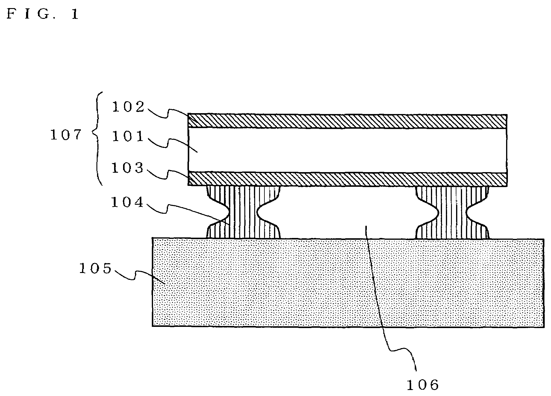
[0045]FIG. 1 is a cross-sectional view schematically showing a structure of an acoustic resonator according to an embodiment of the present invention. The acoustic resonator shown in FIG. 1 includes a substrate 105, a support section 104 provided on the substrate 105, a lower electrode 103 provided on the support section 104, a piezoelectric body 101 provided on the lower electrode 103, and an upper electrode 102 provided on the piezoelectric body 101. The lower electrode 103, the piezoelectric body 101 and the upper electrode 102 form a vibration section 107. An area surrounded by the substrate 105, the support section 104 and the lower electrode 103 acts as a cavity 106. The cavity 106 is a space provided in order not to prevent the excitation of the thickness longitudinal vibration of the vibration 107.

[0046]The piezoelectric body 101 is formed of a piezoelectric material such as, for example, aluminum nitride (AlN), zinc oxide ...


PUM


Abstract

An acoustic resonator includes a substrate, a support section provided on the substrate, a lower electrode provided on the support section, a piezoelectric body provided on the lower electrode, and an upper electrode provided on the piezoelectric body. The lower electrode, the piezoelectric body and the upper electrode form a vibration section. The support section for supporting the vibration section is shaped such that at least one portion of a vertical cross-section thereof has a curvature.

Description

BACKGROUND OF THE INVENTION[0001]1. Field of the Invention[0002]The present invention relates to a device including a piezoelectric thin film and a method for producing such a device, and more specifically to an acoustic resonator and a micromachine switch usable in an radio frequency circuit of mobile communication terminals such as mobile phones, wireless LAN apparatuses and the like, and a method for producing the same.[0003]2. Description of the Background Art[0004]Components built in electronic apparatuses such as mobile phones and the like are demanded to be compact, lightweight, and small in loss and to provide high reliability. For fulfilling such demands, various types of devices including a piezoelectric thin film have been proposed. Devices expected to be compact, lightweight and small in loss are, for example, filters and micromachine switches using an acoustic resonator.[0005]FIG. 13A is a cross-sectional view of an exemplary conventional acoustic resonator (see, for ex...

Claims


Application Information

Patent Timeline
Patent Type & Authority Patents(United States)
IPC IPC(8): H03H9/05H01H57/00H03H9/54H03H9/70H02N2/00
CPCH01H57/00H03H9/173H03H3/02H01H2057/006H03H2003/021
Inventor NAKATSUKA, HIROSHIONISHI, KEIJIYAMAKAWA, TAKEHIKOIWASAKI, TOMOHIROKAMIYAMA, TOMOHIDE
Owner PANASONIC CORP
Learn More