
Receiver

a receiver and receiver technology, applied in the field of receivers, can solve the problems of reducing the level of the signal component associated with analog broadcasting, affecting the reception status, and worsening of the wave, so as to prevent the s/n ratio from decreasing

Inactive Publication Date: 2009-11-24
MITSUBISHI ELECTRIC CORP
View PDF7 Cites 6 Cited by
  • Summary
  • Abstract
  • Description
  • Claims
  • Application Information

AI Technical Summary

Benefits of technology

Enables proper determination of digital signal reception without reducing the S / N ratio during analog signal reception and ensures accurate signal processing by selectively demodulating either the analog or digital signal based on receive levels, thereby maintaining signal quality.

Problems solved by technology

A problem with related art receivers constructed as mentioned above is that while they can easily receive digital broadcasting waves since they attenuate only a signal component associated with analog broadcasting by using a BEF, in a case where digital broadcasting waves are located in both sides (i.e., a high-frequency side and a low-frequency side) of an analog broadcasting wave, they may determine that they can receive the digital broadcasting waves even when a multi-pass or the like occurs in one of the digital broadcasting waves and the status of reception of the digital broadcasting wave gets worse since they determine the receive level of the digital broadcasting by measuring the levels of the digital broadcasting waves in the both sides of the analog broadcasting wave.
Another problem with related art receivers is that in a case of reception of analog broadcasting, since related art receivers attenuate only a signal component associated with the analog broadcasting by using a BEF, as mentioned above, the level of the signal component associated with the analog broadcasting decreases and therefore the signal-to-noise (S / N) ratio decreases.

Method used


Image

  • Receiver
  • Receiver
  • Receiver

Examples


embodiment 1

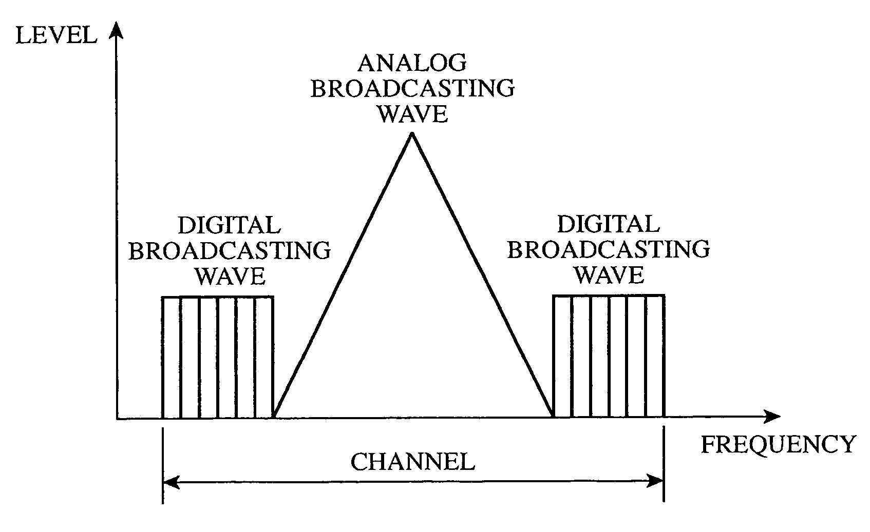
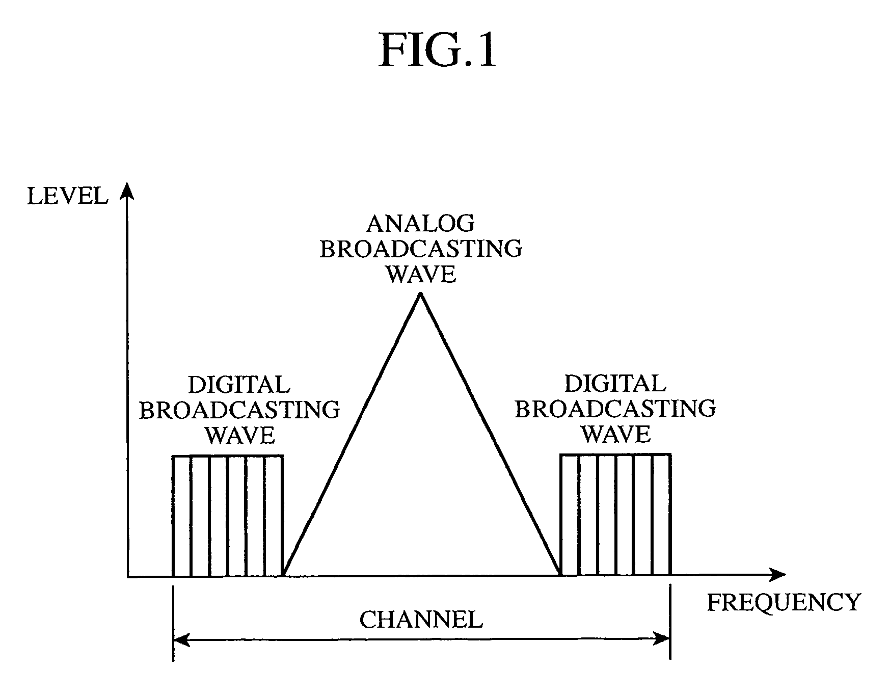
[0022]First, a system in which analog broadcasting waves and digital broadcasting waves are simultaneously transmitted will be explained with reference to FIG. 1 by taking an IBOC system as an example. FIG. 1 is a diagram showing a power spectrum distribution at a time of transmission of analog broadcasting waves and digital broadcasting waves in the IBOC system. In FIG. 1, the horizontal axis shows frequencies and the vertical axis shows the intensity (i.e., level) of the power spectrum of the broadcasting waves.

[0023]The horizontal axis shows an offset from the center frequency of an analog broadcasting wave (for example, an FM signal audio broadcasting wave) which is set to a point of origin. A digital broadcasting wave is transmitted using a frequency range between analog broadcasting waves, and the digital broadcasting wave has the same center frequency as the analog broadcasting waves and has a power spectrum which is distributed outside the power spectrum of an analog broadca...


PUM


Abstract

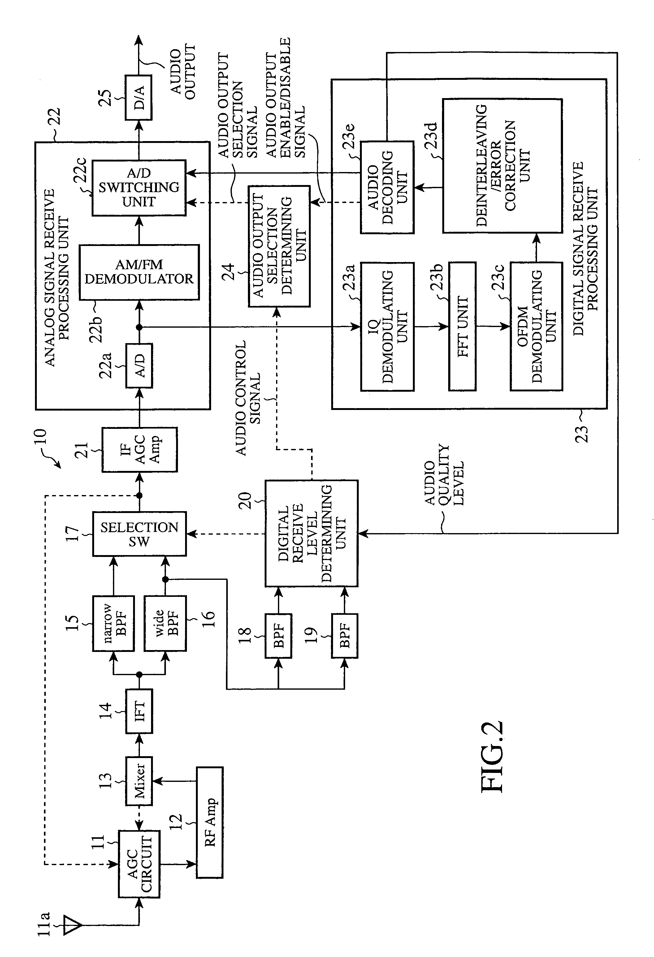
A receiver accepts a digital signal having an upper side digital signal located in a higher frequency range on a frequency axis than an analog signal, and a lower side digital signal located in a lower frequency range on the frequency axis than the analog signal. A BPF (15) allows the analog signal to pass therethrough and a BPF (16) allows the analog signal and the digital signal to pass therethrough. BPFs (18) and (19) accept the output of the BPF (16) and output the upper side digital signal and the lower side digital signal, respectively. A digital receive level determining unit (20) and a selection SW (17) select either of the outputs of the BPFs (15) and (16) according to the receive levels of the upper side digital signal and the lower side digital signal, and output the selected output as a selected signal. The receiver then demodulates this selected signal.

Description

BACKGROUND OF THE INVENTION[0001]1. Field of the Invention[0002]The present invention relates to a receiver for use in a transmission system in which an analog signal and a digital signal are simultaneously transmitted at the same center frequency. More particularly, it relates to a receiver that selectively receives either an analog signal or a digital signal.[0003]2. Description of Related Art[0004]In general, a receiver that selectively receives either an analog signal or a digital signal in a transmission system in which the analog signal and the digital signal are simultaneously transmitted at the same center frequency is known. For example, there has been proposed a broadcast system called an IBOC (In Band On Channel) system by U.S. iBiquity, as a broadcast system in which an analog broadcasting wave and a digital broadcasting wave are simultaneously broadcast by an identical broadcasting station.[0005]In this IBOC system, a digital broadcasting wave is transmitted via a chann...

Claims


Application Information

Patent Timeline
Patent Type & Authority Patents(United States)
IPC IPC(8): H04M1/00H04B1/26H04B1/12H04B1/16H04B7/00
CPCH04B1/123H04B1/1638H04H40/18H04H20/30H04L1/004H04H2201/183
Inventor NAGANO, SOICHINAGAHAMA, HIROYUKI
Owner MITSUBISHI ELECTRIC CORP
Learn More