
Engine system including multipe engines and method of operating same

a multi-engine, engine technology, applied in combination engines, machines/engines, electric control, etc., can solve the problems of different operation of cylinders, affecting the operation of the engine system, and consuming valuable space in the engine system of ammonia tanks

Inactive Publication Date: 2009-12-01
CATERPILLAR INC
View PDF14 Cites 13 Cited by
  • Summary
  • Abstract
  • Description
  • Claims
  • Application Information

AI Technical Summary

Benefits of technology

This approach allows for effective on-board ammonia generation without compromising engine performance, reducing NOx emissions efficiently and eliminating power imbalances, thus addressing the limitations of existing systems.

Problems solved by technology

Although these systems can reduce NOx emissions, NOx selective catalytic reduction systems often require ammonia storage on the vehicle.
Ammonia tanks can consume valuable space within the engine system and must be replenished periodically.
Further, because of the high reactivity of ammonia, on-board storage of the ammonia can be hazardous.
Although the Kinugasa method allows for on-board generation of ammonia, the different operations of the cylinders can create drawbacks.
For instance, an engine may function less efficiently and with lower power output when rich combustion occurs in a portion of the cylinders.
Moreover, the two cylinder groups, operating in the Kinugasa method, may cause significant power imbalance within the engine, resulting in engine vibrations.

Method used


Image

  • Engine system including multipe engines and method of operating same
  • Engine system including multipe engines and method of operating same
  • Engine system including multipe engines and method of operating same

Examples


Embodiment Construction

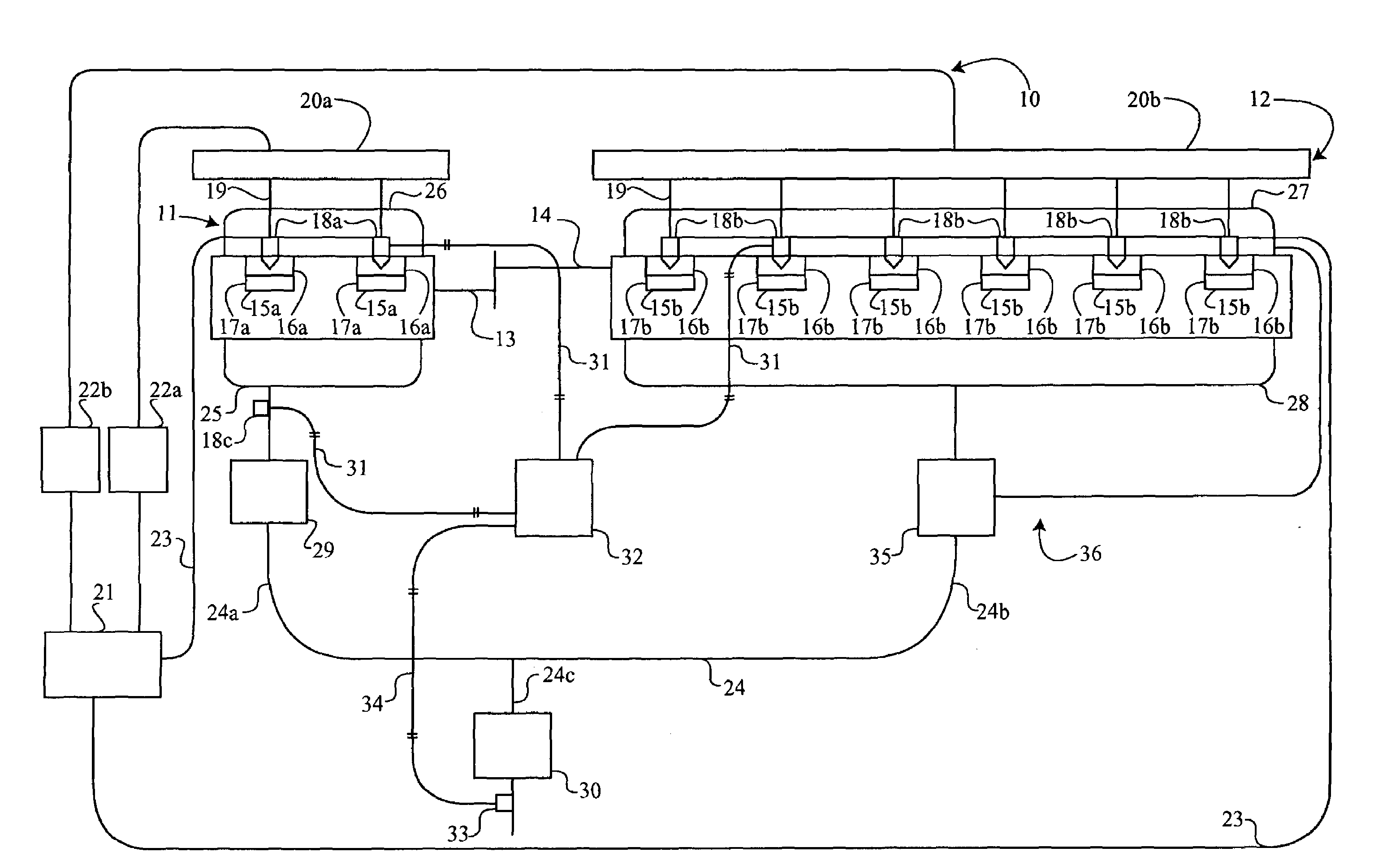
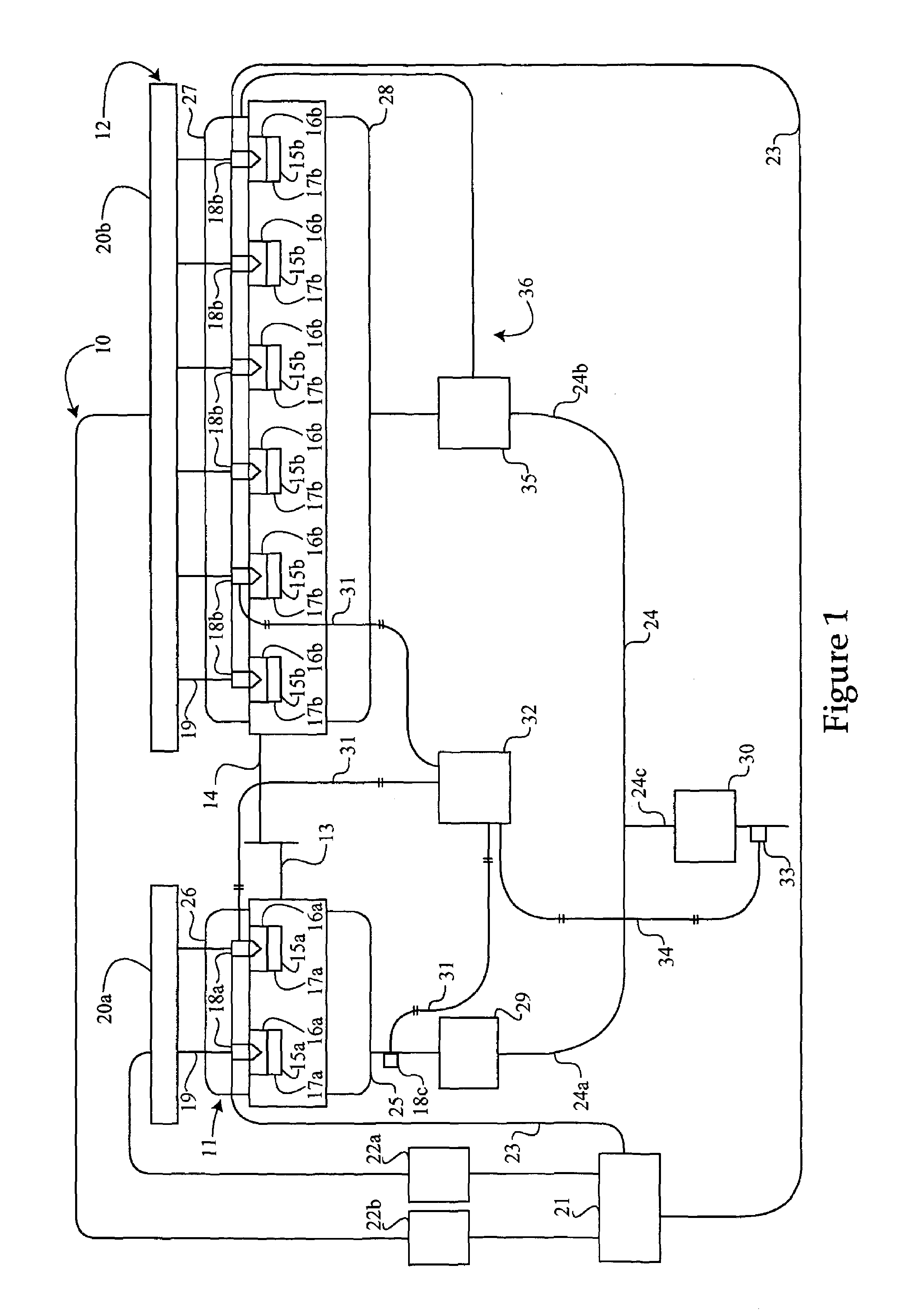
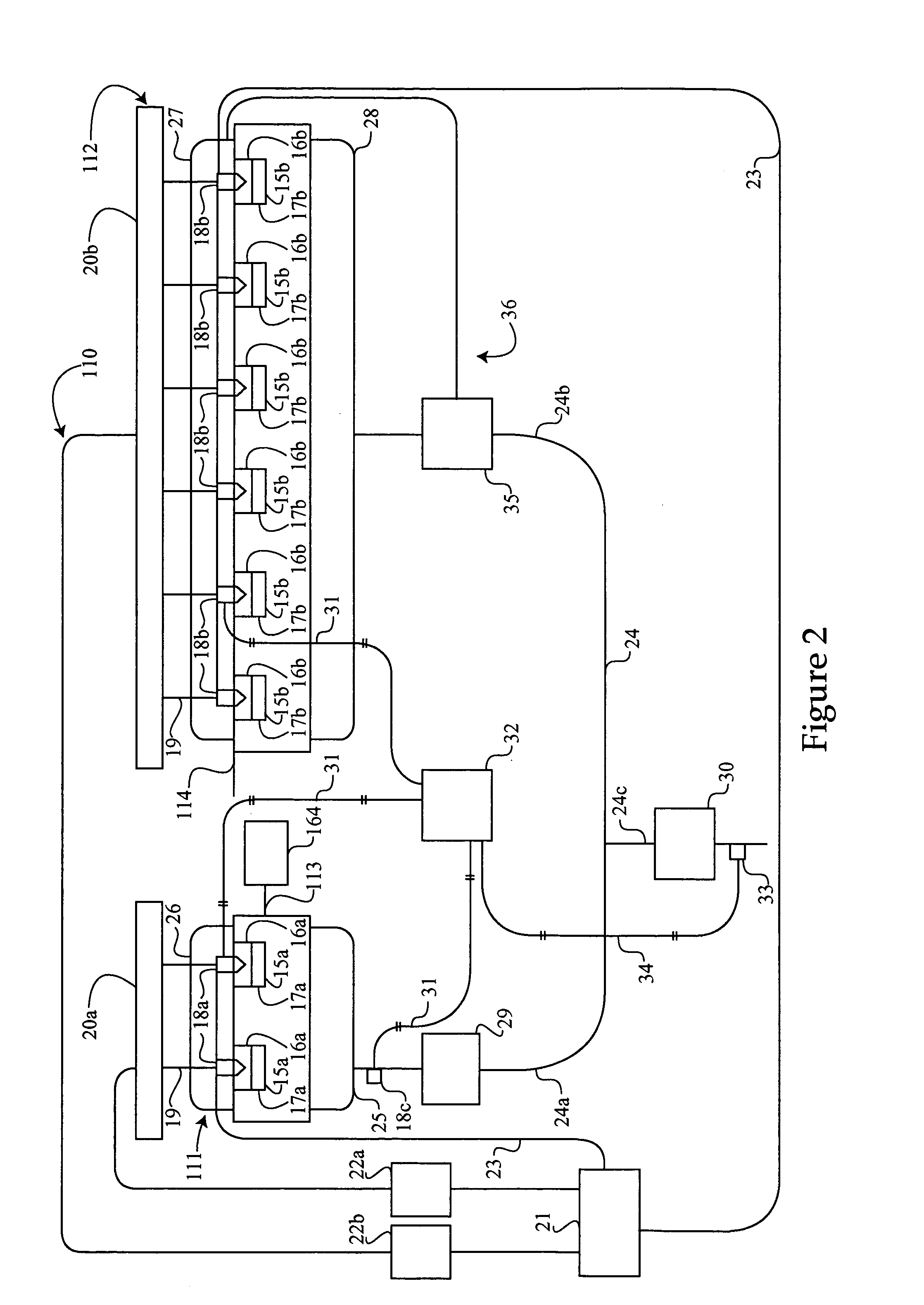
[0014]Referring to FIG. 1, there is shown a schematic representation of an engine system 10, according to a first embodiment of the present disclosure. The engine system 10 includes a first engine 11 operable to produce a high NOx concentration 65 (illustrated in FIG. 6) and a second engine 12 operable to produce a low NOx concentration 37 (illustrated in FIG. 6). Although the present disclosure is illustrated as including only two engines 11 and 12, it should be appreciated that the engine system could including any number of engines, as long as at least one engine produces exhaust with the high NOx concentration and at least one engine produced exhaust with the low NOx concentration. In the illustrated embodiment, the first engine 11 may be a low displacement engine, and the second engine 12 may be a high displacement engine.

[0015]The first engine 11, being the low displacement engine, may include various types of engines, including but, not limited to, a Stirling-cycle engine, a ...


PUM


Abstract

Engines that include different combustion strategies for different cylinders may create a power imbalance resulting in undesirable engine vibrations. The engine system of the present disclosure includes a first engine that is operable to produce a high NOx concentration exhaust and a second engine that is operable to produce a low NOx concentration exhaust. The first engine is fluidly connected to a first section of an exhaust passage and the second engine is fluidly connected to a second section of the exhaust passage. The exhaust from the first engine and the exhaust from the second engine are merged in a merged section of the exhaust passage downstream from both the first and second sections of the exhaust passages. The high NOx concentration exhaust may be converted to ammonia for reacting with the low NOx concentration exhaust to arrive at very low NOx concentration from the merged exhaust.

Description

TECHNICAL FIELD[0001]The present disclosure relates generally to engine systems with multiple engines, and more specifically to combining exhaust passages from the multiple engines within an engine system for exhaust purification.BACKGROUND[0002]In order to meet increasingly stringent federal regulations of NOx and other undesirable emissions, engineers are constantly seeking new strategies of reducing the undesirable emissions. One method of reducing NOx emissions is NOx selective catalytic reduction (SCR) systems. These systems use ammonia (NH3) to reduce NOx to nitrogen (N2) and water. Although these systems can reduce NOx emissions, NOx selective catalytic reduction systems often require ammonia storage on the vehicle. Ammonia tanks can consume valuable space within the engine system and must be replenished periodically. Further, because of the high reactivity of ammonia, on-board storage of the ammonia can be hazardous.[0003]Some of the drawbacks associated with the use of NOx ...

Claims


Application Information

Patent Timeline
Patent Type & Authority Patents(United States)
IPC IPC(8): F01N3/00F01N13/10
CPCF01N3/2073F02M47/027F02B73/00F02D41/146F02M45/086F02M61/1813F02M61/182F02M63/0064F01N13/011F01N2240/25F01N2240/30F01N2560/026F01N2560/14F01N2610/02F01N2610/03F02B37/00F02D41/029F02D41/1498F02M2200/46F01N13/107
Inventor DRISCOLL, JOSHROBEL, WADE J.BLOMS, JASON
Owner CATERPILLAR INC
Learn More