Sand dispenser for a scarifier

a technology of sand dispenser and scarifier, which is applied in the direction of potato planters, broadcast seeders, and sowing, can solve the problems of difficult sand directing into the groove, and achieve the effect of facilitating the free flow of sand

Active Publication Date: 2009-12-01
GRADEN INDS
View PDF10 Cites 3 Cited by
  • Summary
  • Abstract
  • Description
  • Claims
  • Application Information

AI Technical Summary

Benefits of technology

[0004]Topdressing is a significant part of turf maintenance. Topdressing replaces the thatch layer removed by the scarifier with sand, which allows water and nutrients to access the root zone of the grass. This quickens grass germination and healing, and in general is an important agronomic practice.
[0012]The ends of the distributing lines preferably each include a tube and a guide at the end of the tube that is adapted, in use, to protrude into the groove. The guide is preferably rigid and has a forward face that, in use, pushes debris and organic matter out of the groove before sand is dispensed therein. The tube tapers from a circular cross section at an upper part to an elliptical cross section at the end of the tube. Preferably the end of the tube is cut at an angle to facilitate free flow of sand into the groove.

Problems solved by technology

The problem with such machines is that it is difficult to direct sand into the grooves.
Additionally, the wheels of these machines tend to drive over and close the grooves, which is undesirable.

Method used


Image

  • Sand dispenser for a scarifier
  • Sand dispenser for a scarifier
  • Sand dispenser for a scarifier

Examples


Embodiment Construction

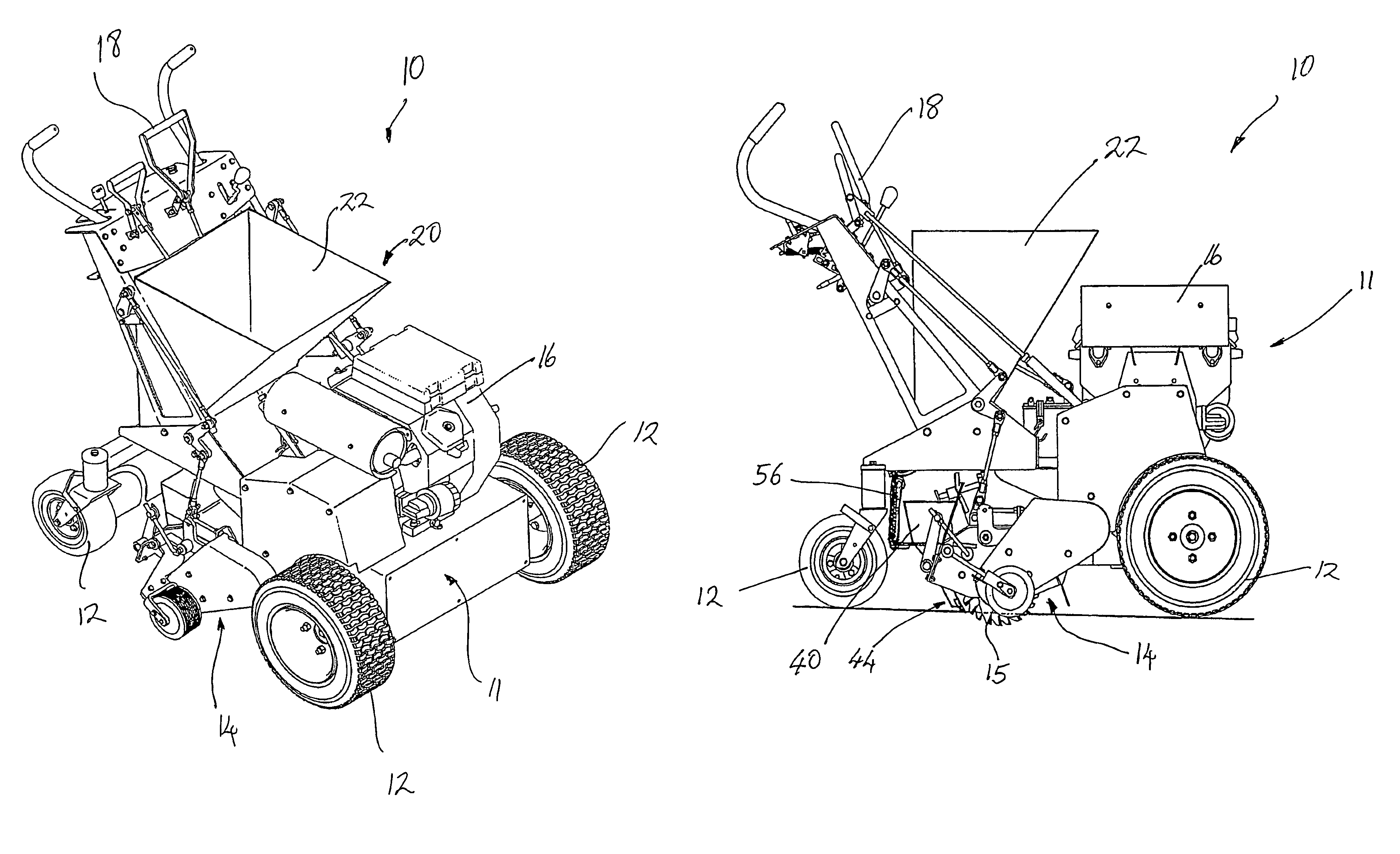
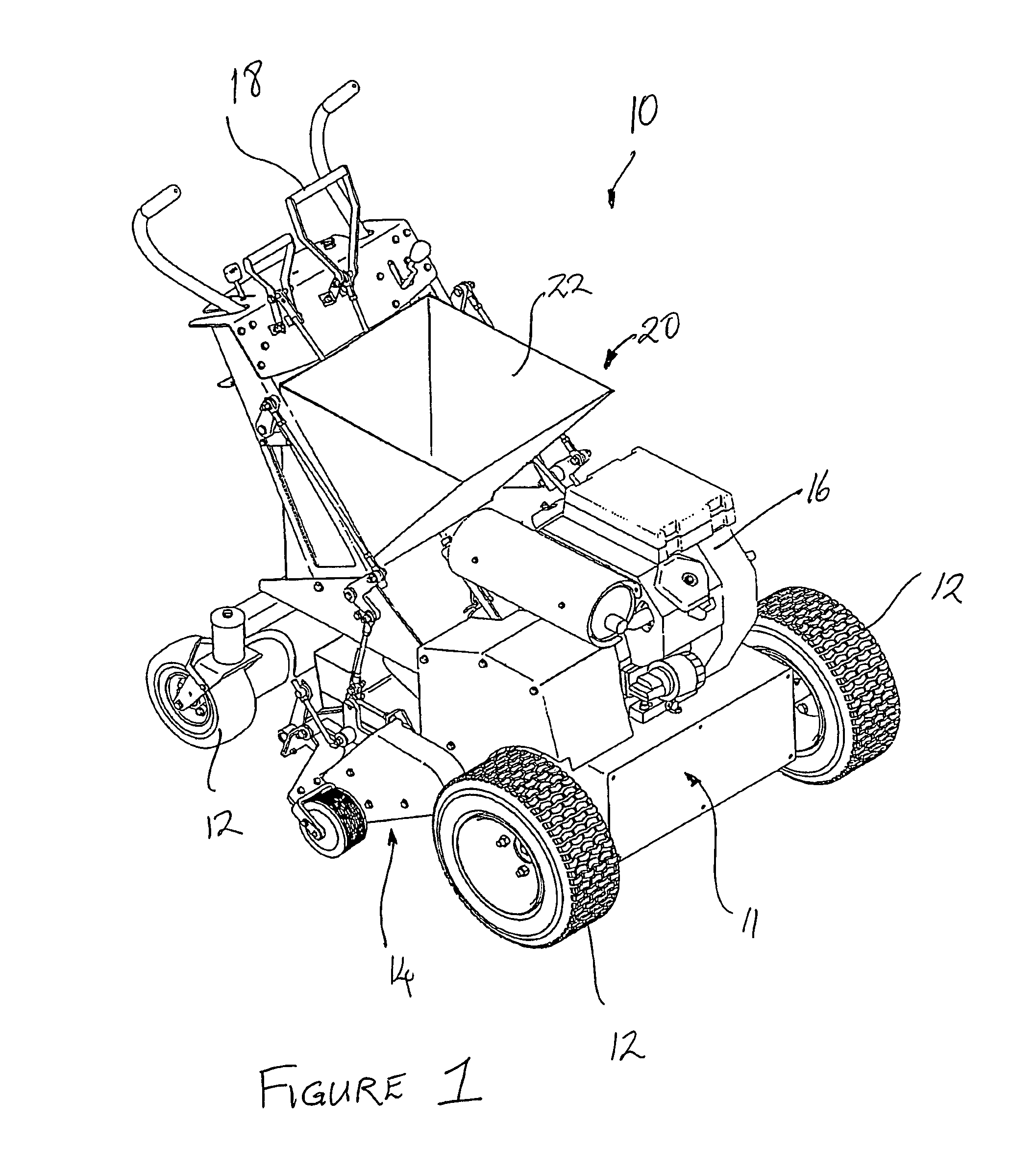
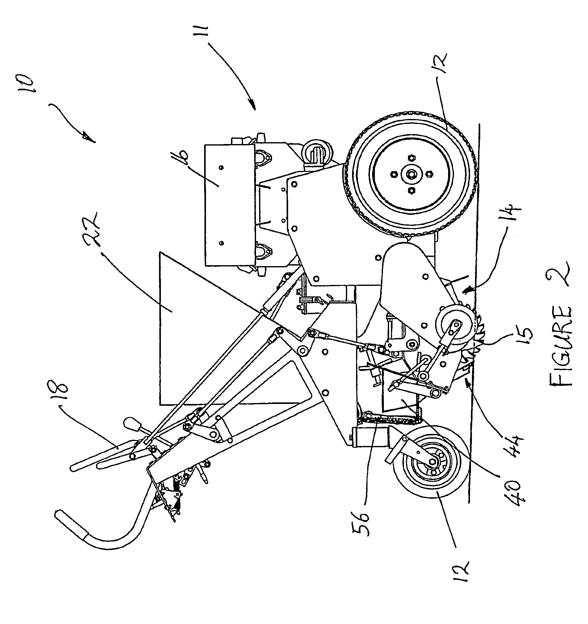
[0034]FIGS. 1 and 2 illustrates a pedestrian scarifier 10 having a scarifier structure 11 supported on four wheels 12 and a rotor assembly 14 supported by a rotor housing 13 that is height adjustable relative to the scarifier structure 11 for raising and lowering cutting blades 15 of the rotor assembly 14. Blades 15 are aligned in a row spaced on a rotor shaft (not shown) that is driven by an engine 16.

[0035]FIG. 2 illustrates rotor assembly 14 in a lowered operating position where blades 15 engage and cut grooves into the ground. Hand lever 18 is pivoted by a user to raise rotor assembly 14 off the ground into an inoperative position (not shown).

[0036]A sand dispenser 20 is mounted onto the scarifier 10 and in use dispenses a controlled flow of sand behind blades 15 and into the grooves newly formed by the blades. The sand dispenser 20 dispenses an appropriate amount of sand for the depth of grooves created and drops the sand directly into the groove.

[0037]FIGS. 3 and 4 illustrates...


PUM


Abstract

A sand dispenser for a scarifier wherein the sand dispenser is mounted on the scarifier and comprises: a sand hopper having an outlet at a lower end of the hopper; a gate located below the outlet and moveable between an open position and a closed position for controlling the flow of sand through the hopper and into a distributor, the distributor including a row of distributing lines through which sand is directed to flow and enter grooves in the ground created by blades of the scarifier, wherein each distributing line is aligned with a groove.

Description

[0001]This Application is the U.S. National Stage Application under 35 U.S.C. 371 of International Application PCT / AU2006 / 000058 filed Jan. 18, 2006, and claims the foreign filing benefit from Australian patent application number 2005900213 filed Jan. 18, 2005, the complete disclosures of which are incorporated herein by reference.[0002]The present invention relates to a sand dispenser for a scarifier. Moreover, the sand dispenser can be used for a tractor mounted scarifier and for a pedestrian scarifier, examples of which are disclosed in applicant's co-pending international application publication no. WO 2005 / 029940, which is incorporated herein by reference.[0003]The use of scarifiers in maintaining healthy turf surfaces by aerificating and dethatching turf is important. Scarifiers physically remove organic matter in the form of old roots and other plant matter that accumulates in the upper portion of the soil profile. By using a blade to cut a path into the surface profile the o...

Claims


Application Information

Patent Timeline
Patent Type & Authority Patents(United States)
IPC IPC(8): A01C7/00A01C15/00A01C7/08A01C9/00
CPCA01G1/12A01B45/026Y10S111/90A01G20/40A01G20/30A01B45/00
Inventor DRYDEN, GRAHAM
Owner GRADEN INDS
Why Eureka
Try Eureka