Magnetic recording head including main magnetic pole layer, return path layer, and coil layer
a recording head and magnetic technology, applied in the field of magnetic recording heads, can solve problems such as avoiding one or more of them, and achieve the effect of improving recording efficiency and recording efficiency
- Summary
- Abstract
- Description
- Claims
- Application Information
AI Technical Summary
Benefits of technology
Problems solved by technology
Method used
Image
Examples
first embodiment
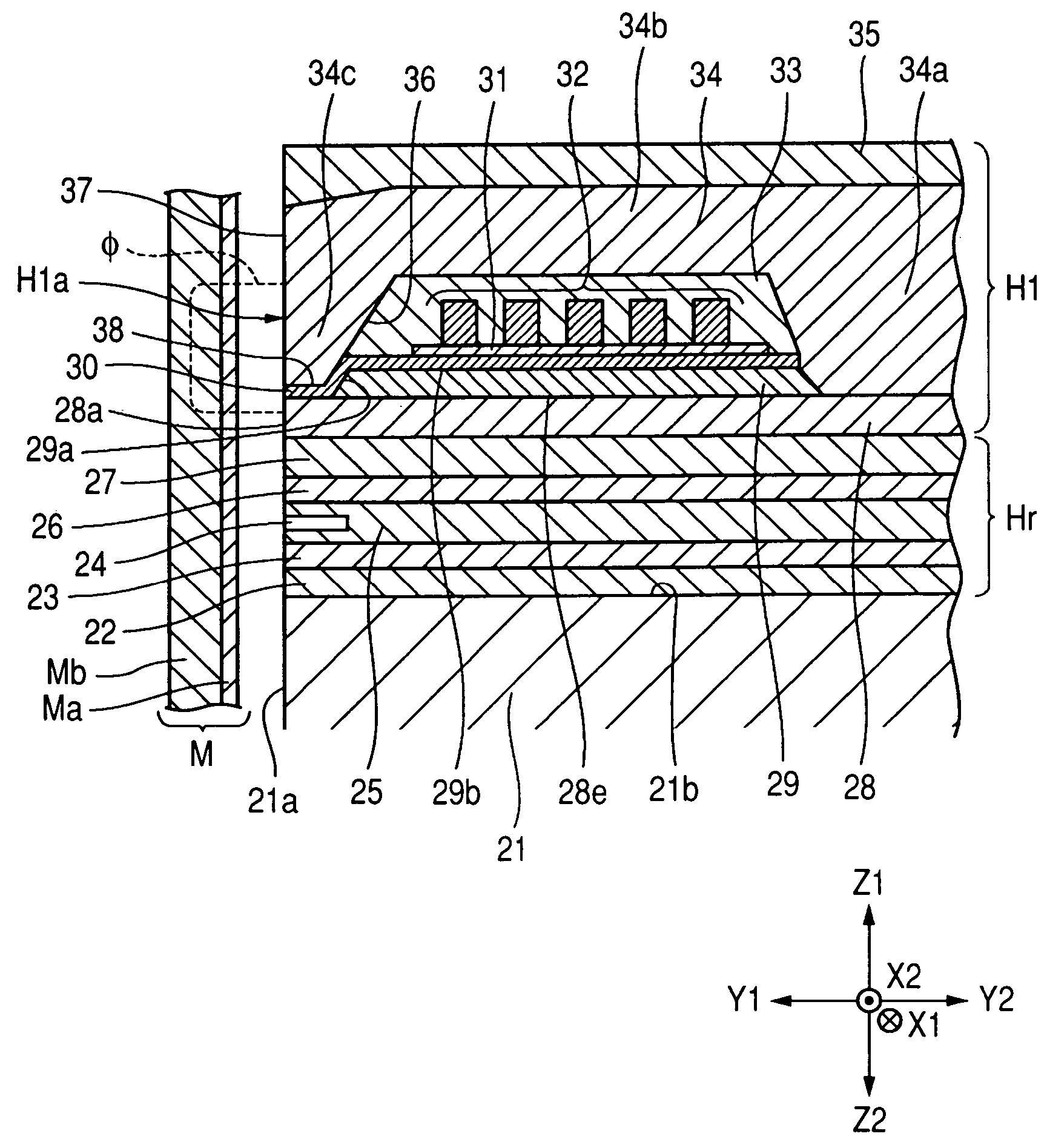
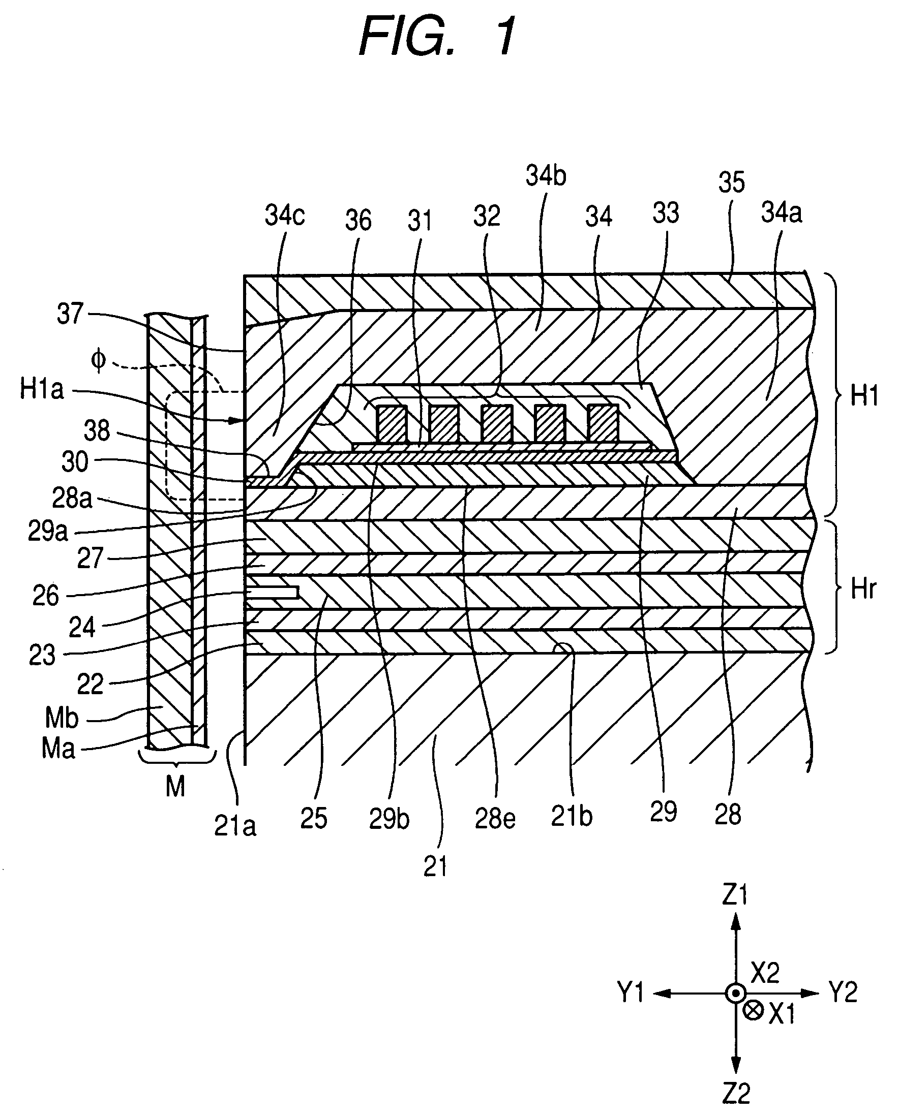
[0049]FIG. 1 is a partial perpendicular magnetic recording cross-sectional view illustrating a configuration of a perpendicular magnetic recording head according to a magnetic recording head of the invention.
[0050]A perpendicular magnetic recording magnetic recording head H1 shown in FIG. 1 applies perpendicular magnetic recording magnetic field to a recording medium M and magnetizes a hard film Ma of the recording medium M.
[0051]The recording medium may be, for example, a disc and include a hard film Ma with high coercivity on the surface and a soft film Mb with high magnetic permeability inside the hard film Ma. Further, the disc rotates about its central axis.
[0052]A slider 21 is formed of a nonmagnetic material, such as Al2O3, Ti, or the like, and a facing surface 21a faces the recording medium M. If the recording medium M rotates, the slider 21 rises from the surface of the recording medium M due to airflow on the surface or slides on the recording medium M.
[0053]A nonmagnetic-...
second embodiment
[0086]FIG. 3 is an exploded perpendicular magnetic recording cross-sectional view showing a configuration of a perpendicular magnetic recording head according a magnetic recording head on the invention.
[0087]A perpendicular magnetic recording head H2 shown in FIG. 3 includes the same components as the perpendicular magnetic recording head H1 shown in FIG. 1. Therefore, in the perpendicular magnetic recording head H2, the same components as in the perpendicular magnetic recording head H1 are designated by the same reference numerals and not described below.
[0088]The perpendicular magnetic recording head H2 shown in FIG. 3 is different from the perpendicular magnetic recording head H1 shown in FIG. 1 as for the shape of the extending front end portion 34c defined in the return path layer 34. As shown in FIG. 3, at a facing surface H2a, the main magnetic pole layer 28 faces the extending front end portion 34c of the return path layer 34 through the gap layer 30, that is, at a predeterm...
third embodiment
[0090]FIG. 4 is an exploded perpendicular magnetic recording cross-sectional view illustrating a configuration of a perpendicular magnetic recording head according to a magnetic recording head of the invention.
[0091]A perpendicular magnetic recording head H3 shown in FIG. 4 includes the same components as the perpendicular magnetic recording head H1 shown in FIG. 1. In the perpendicular magnetic recording head H3, the same components as in the perpendicular magnetic recording head Hi shown in FIG. 1 are designated by the same reference numerals and not described below.
[0092]The perpendicular magnetic recording head H3 shown in FIG. 4 has a difference from the perpendicular magnetic recording head H1 shown in FIG. 1 that the main magnetic pole layer 28, yoke layer 29, gap layer 30, coil layer 32, and return path layer 34 are formed upward (Z1-Z2 direction on the separating layer 27 (in the Z1 direction in FIG. 1) in the reverse order).
[0093]For example, as shown in FIG. 4, the perpen...
PUM
| Property | Measurement | Unit |
|---|---|---|
| height | aaaaa | aaaaa |
| thickness | aaaaa | aaaaa |
| recording magnetic field | aaaaa | aaaaa |
Abstract
Description
Claims
Application Information
 - R&D
- Intellectual Property
- Life Sciences
- Materials
- Tech Scout
- Unparalleled Data Quality
- Higher Quality Content
- 60% Fewer Hallucinations
Browse by: Latest US Patents, China's latest patents, Technical Efficacy Thesaurus, Application Domain, Technology Topic, Popular Technical Reports.
© 2025 PatSnap. All rights reserved.Legal|Privacy policy|Modern Slavery Act Transparency Statement|Sitemap|About US| Contact US: help@patsnap.com


