Package terminal air conditioner system and associated methods

a terminal air conditioner and air conditioning system technology, applied in the field of air conditioning and handling systems and methods, can solve the problems of not being able to maintain humidity levels within the space, not being able to condition outside makeup air, and ptacs typically providing unconditioned outside, so as to reduce the outside air temperature and humidity, and control the indoor air quality of the spa

Active Publication Date: 2009-12-08
R E HANSEN IND INC DBA ISLANDAIRE
View PDF13 Cites 8 Cited by
  • Summary
  • Abstract
  • Description
  • Claims
  • Application Information

AI Technical Summary

Benefits of technology

[0010]The system is useful for the introduction of outside air through a PTAC unit by reducing the outside air temperature and humidity of the outside makeup air. In this case a separate controllable mechanism is provided for reducing the temperature of the outdoor air (sensible cooling) and dehumidifying the air (latent cooling) prior to entering the space

Problems solved by technology

PTACs are thermostatically controlled to maintain the desired temperature in the space but have no means to condition outside makeup air nor to maintain humidity levels within the space.
PTACs typically provide unconditioned outside air to hotel rooms or other spaces through an opening in the back of the unit.
This results in the potential for mold and mildew growt

Method used


Image

  • Package terminal air conditioner system and associated methods
  • Package terminal air conditioner system and associated methods
  • Package terminal air conditioner system and associated methods

Examples


first embodiment

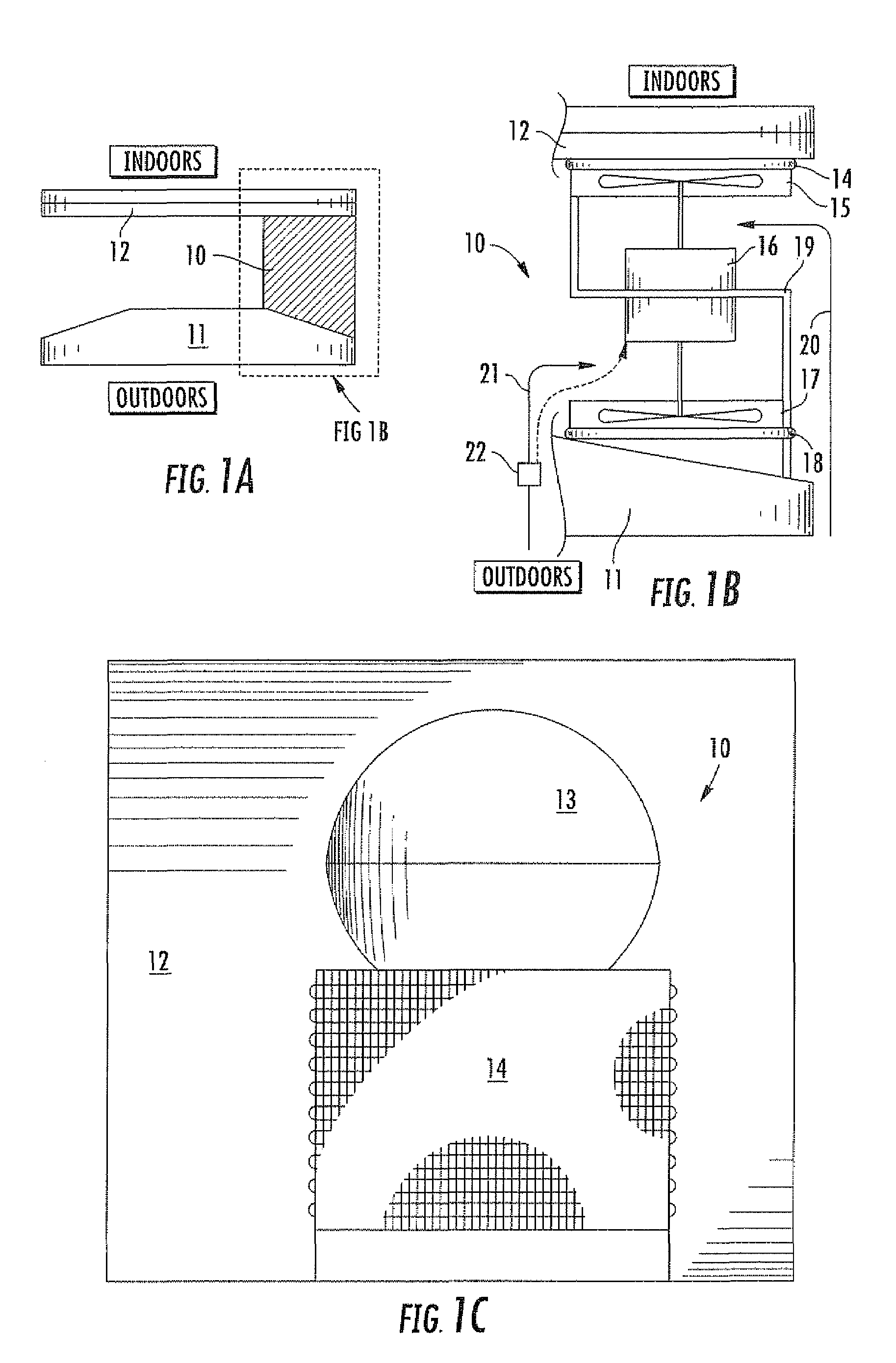
[0023]a PTAC system 10 is illustrated in FIGS. 1A-1D. In FIG. 1A the unit 10 is shown as being positioned between the elements of an existing air conditioning unit comprising a condenser coil, fan, and shroud 11 on the inside and an evaporator coil 12 on the outside.

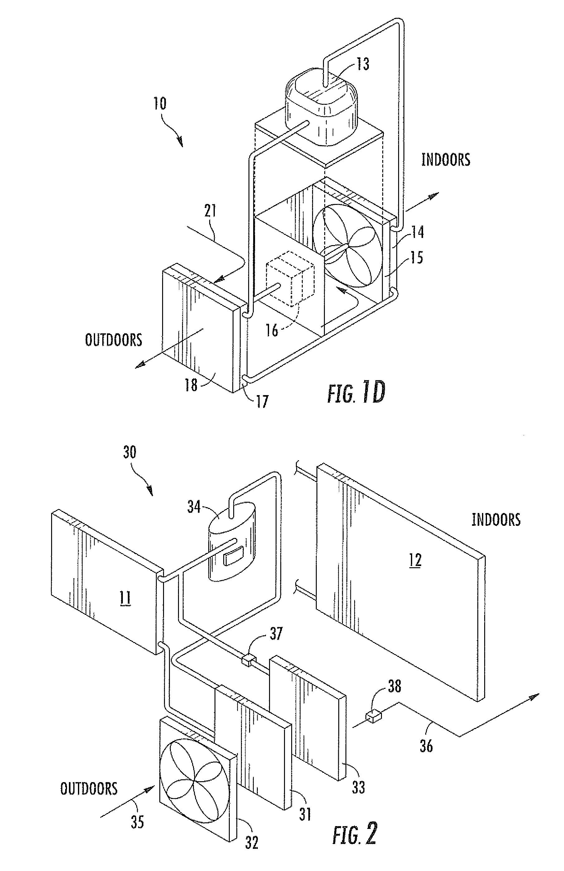
[0024]The area encompassing the unit 10 positioned as in FIG. 1A, as indicated by the dashed rectangle, is illustrated in plan view in FIG. 1B. An elevation view is given in FIG. 1C, and a schematic isometric view in FIG. 1D. The unit, connected together in conventional fashion, comprises a compressor 13, evaporator coil 14, evaporator fan 15, fan motor 16, condenser fan 17, and condenser coil 18. The evaporator coil 14 is mounted directly to the outside air opening in the existing PTAC unit 11,12, which typically comprises a 4×4 in. opening. A metal plate 19 is provided for air path separation adjacent the fan motor 16. The makeup air flow path 20 is shown to lead to the evaporator fan 15; the heat removal air flow path...

third embodiment

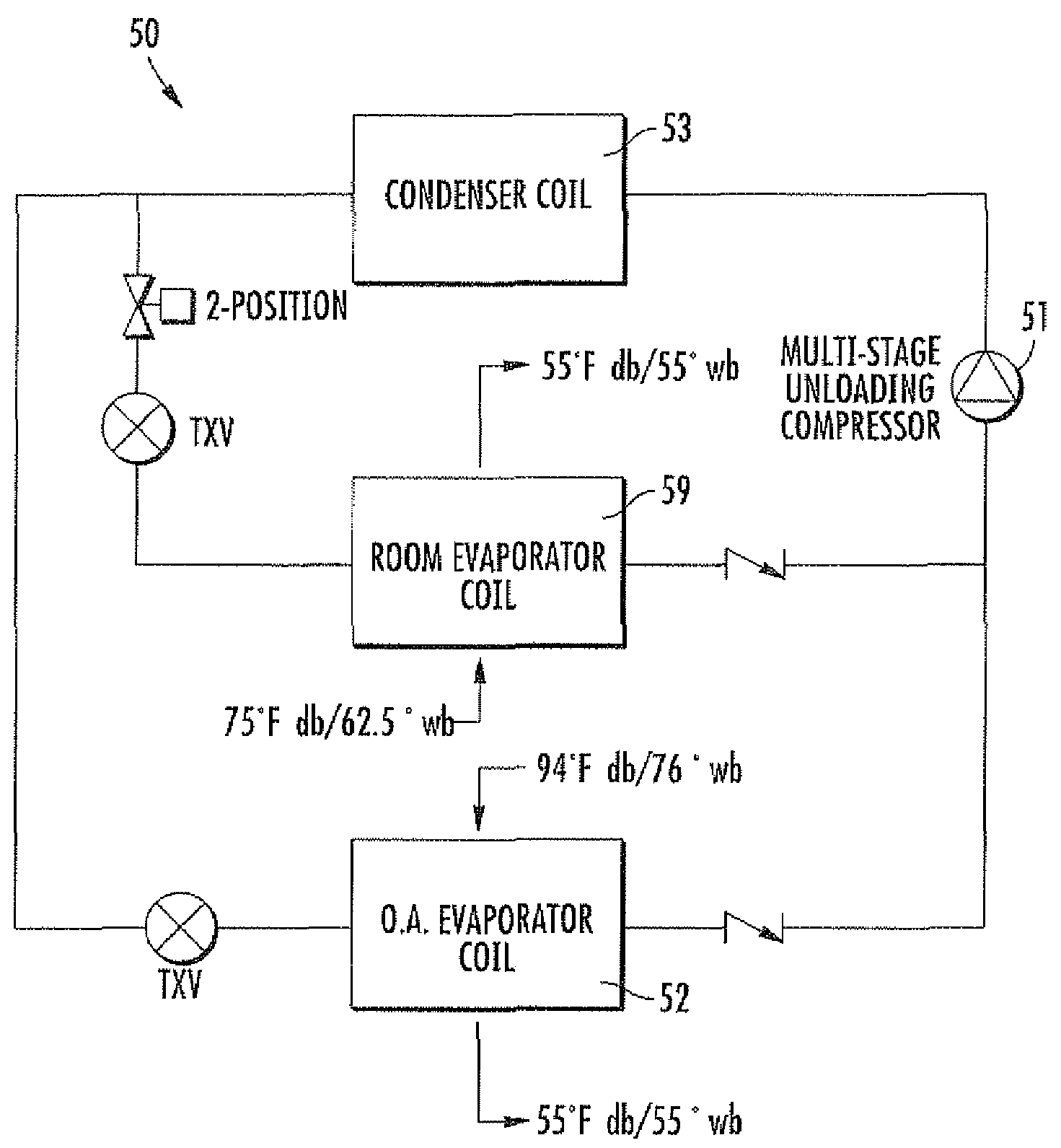
[0027]a PTAC unit 50, illustrated in FIGS. 3A-3C, comprises a single compressor 51 at the heart of both refrigeration systems. This system 50 is believed to represent a preferable system to those 10,30 discussed above, which are intended for retrofit applications. The compressor 51 preferably comprises a multi-stage unloading compressor, which can maintain the PTAC's thermostat setting for the space and provide the required cooling-dehumidifying for the add-on evaporator coil 52. All heat rejection can be provided through a single condenser coil 53.

[0028]The system 50 further comprises a fan motor 54 for the evaporator fan 55 and condensor fan 56 and a fan motor 57 for the add-on evaporator coil fan 58. An evaporator coil 59 is provided adjacent the indoor face of the unit 50. Air flow 60 from the outside reaches the condenser coil 53 and fan 56; air flow 61 from the outside also reaches the add-on evaporator coil 52 and fan 58. Air flow 62 from indoors reaches the evaporator fan 55...


PUM


Abstract

An air conditioning unit is for cooling and dehumidifying outside air for flowing into an enclosed space from outside. The unit is interposable between a first evaporator coil and a first condenser coil and comprises a second evaporator coil that is positioned to receive outside air for channeling therethrough from an outer to an inner side and thence to the enclosed space. A second condenser coil is positioned to receive outside air for channeling therethrough from an inner to an outer side and thence to the outside. A compressor is in fluid communication with and upstream of the second condenser coil and downstream of the second evaporator coil. Another embodiment is intended as a unitary system and includes a unitary compressor and condenser coil, with one evaporator coil for processing inside air and another for channeling outside air into the enclosed space.

Description

CROSS-REFERENCE TO RELATED APPLICATION[0001]This application claims priority to provisional application Ser. No. 60 / 673,908, filed on Apr. 22, 2005.FIELD OF INVENTION[0002]The present invention generally relates to air conditioning and handling systems and methods, and, in particular, to packaged terminal air conditioning systems and methods.BACKGROUND[0003]Packaged terminal air conditioning (PTAC) units are typically used for cooling air within a space. In a particular embodiment, PTACs can be used to provide space cooling for the hotel industry, which permits the occupant to control of his / her own cooling and heating requirements. PTACs are thermostatically controlled to maintain the desired temperature in the space but have no means to condition outside makeup air nor to maintain humidity levels within the space.[0004]PTACs typically provide unconditioned outside air to hotel rooms or other spaces through an opening in the back of the unit. The air is introduced to the space at a...

Claims


Application Information

Patent Timeline
IPC IPC(8): F25B5/02
CPCF25B5/02F24F3/001
Inventor KRITSKY, WALTERWEINAUG, WILLIAMSYMMES, ROBERT L.MIRUS, BRIAN A.
Owner R E HANSEN IND INC DBA ISLANDAIRE
Why Eureka
Try Eureka