
System and method for mounting a plate to an adhesive member

a technology of adhesive members and mounting plates, applied in the printing industry, can solve the problems of high sleeve cost per unit, uneven alignment of finished products, and high cost of sleeves, and achieve the effect of removing misalignment or skew caused by improperly aligned printing plates

Inactive Publication Date: 2009-12-08
GERALD & TERESA ANN GARTNER OR THEIR SUCCESSORS
View PDF10 Cites 0 Cited by
  • Summary
  • Abstract
  • Description
  • Claims
  • Application Information

AI Technical Summary

Benefits of technology

"The present invention is a system and method for creating a circular printing plate or other flat object that can be inserted into a printing press or other device. It assumes that the printing plate has alignment marks on it to ensure proper alignment. An adhesive member is used to attach the printing plate to the adhesive sheet, leaving a section of the printing plate that is not yet attached. The printing plate and adhesive sheet are then rolled into a circular form and held in place. This method ensures that each printing plate is arranged in a circular format ready to be mounted on a printing press drum, eliminating misalignment or skew caused by improperly aligned printing plates."

Problems solved by technology

In such cases, proper alignment (“registration”) of the printing plates on the drums is essential otherwise, the finished product will have improperly aligned images and colors in addition to improper alignment to the substrate.
While less costly than plate cylinders, sleeves are still quite expensive.
Many printers have cited the benefits of sleeve mounting, but do not use it because of the high sleeve cost per unit and because a large inventory of blank sleeves matched in diameter to the various sizes of plate cylinders in stock must be maintained to accommodate new jobs as they are scheduled.
Substrate and ink waste are usually large expenses to printing companies and they constantly try to minimize this waste.
The same systems are used to mount plates on to plate cylinders or sleeves, so the current use of sleeves does nothing to improve the registration accuracy.
These systems have served the industry well, but they have some limitations.
First, not all cylinders are exactly of the same diameter.
Also, there is no way to assure that the individual who mounts the plates uses the same pressure, which can introduce variability.

Method used


Image

  • System and method for mounting a plate to an adhesive member
  • System and method for mounting a plate to an adhesive member
  • System and method for mounting a plate to an adhesive member

Examples


Embodiment Construction

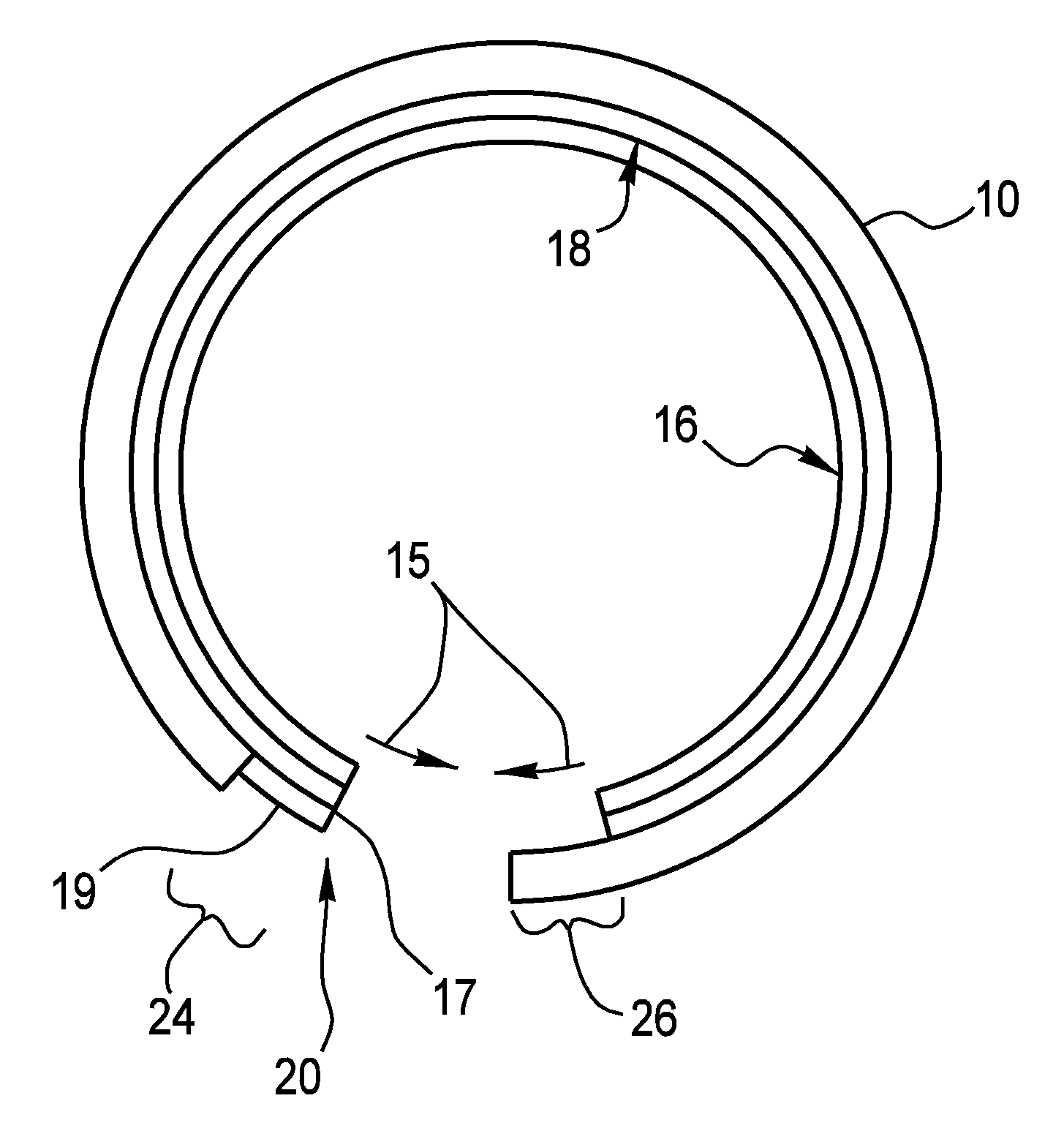
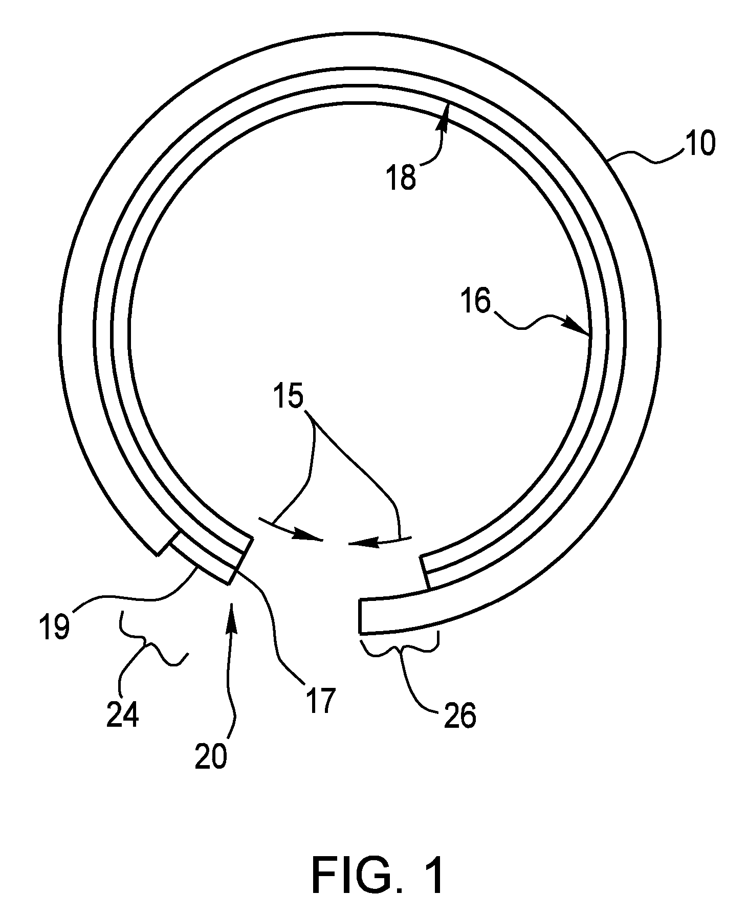
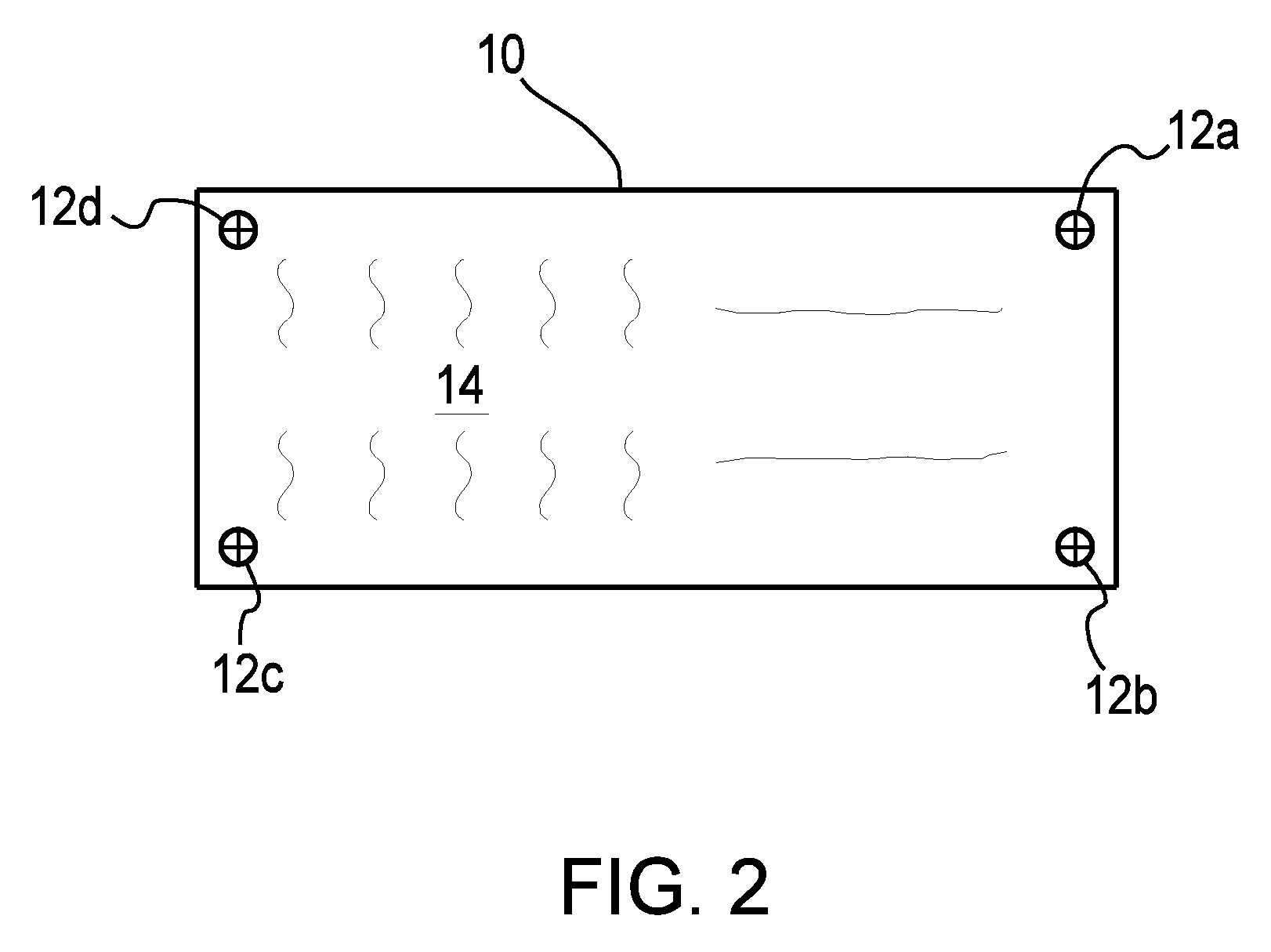
[0022]The present invention features a novel system and method for forming a photographically or digitally generated printing plate or other generally flat, planar object into a circular sleeve that can then be inserted onto the drum of a printing press or other device. The invention assumes that the printing plate 10, FIG. 2, will have imaged or otherwise placed thereon one or more and preferably four (4) alignment marks 12 in addition to the indicia 14 (text and / or images) to be printed. Although the present invention will be explained in connection with the flexography method of printing, this is not a limitation of the present invention.

[0023]Flexography is a “relief” printing process meaning that the image portion of the plate is raised above the “floor” of the plate (such as a rubber stamp). The “letterpress” method is also a relief printing process whereas offset lithography plates are essentially planar and rely on the chemistry of the printing area. The present invention ap...


PUM

PropertyMeasurementUnit
widthaaaaaaaaaa
widthaaaaaaaaaa
lengthaaaaaaaaaa

Abstract

A system and method for adhering and aligning a generally flat, planar object to an adhesive layer, and for facilitating the mounting of the generally flat planar object, such as a printing plate, in near perfect alignment in a cylindrical manner. The method includes providing a generally flat, planar object such as a printing plate and an adhesive member having an adhesive layer at least on one surface. The adhesive member is preferably approximately the same size as the printing plate. The printing plate is mounted to the adhesive member such that there is one edge of the adhesive member which is not initially covered by the printing plate and one edge of the printing plate which overhangs the adhesive member. The combined adhesive member / printing plate structure is next rolled into a cylindrical form and held in place on a device which allows alignment marks on the printing plate to align the two ends of the printing plate prior to the printing plate being fully adhered to the adhesive member. The resulting sleeve structure can then be inserted onto a plate cylinder and this assembly utilized in a printing press. In another embodiment, the adhesive member is provided as a single or multi-layered structure pre-rolled into a generally circular form.

Description

CROSS-REFERENCE TO RELATED APPLICATIONS[0001]This application is related to U.S Patent Application No. 60 / 727,294 filed Oct. 17, 2005 entitled “System And Method For Mounting A Printing Plate Using Sleeves”, which is incorporated fully herein by reference.TECHNICAL FIELD[0002]The present invention relates in one embodiment to the printing industry and more specifically, relates to a method for mounting a printing plate in a circular manner in near perfect alignment more easily and inexpensively, thereby providing near perfect alignment of the resultant printed image.BACKGROUND INFORMATION[0003]The printing industry now nearly exclusively utilizes photographic or digitally imaged printing plates to produce a printed image. Although this invention is primarily aimed at Flexographic printing, it could be used for letterpress and offset printing, rotary screen printing as well as in any operation were it is desirable to wrap a flat planar item around a concave or convex (oval, a round, ...

Claims


Application Information

Patent Timeline
Patent Type & Authority Patents(United States)
IPC IPC(8): B41F1/34B41F13/10B41F21/12B41F21/14B41F27/00B41F27/06B41F27/12B41L1/02B41L47/14
CPCB29C53/382B41F27/005B41N6/02B41F27/1275B41F27/105Y10S101/36
Inventor GARTNER, GERALD J.
Owner GERALD & TERESA ANN GARTNER OR THEIR SUCCESSORS
Learn More